Die casting Tolerance
Linear Dimensions: Standard Tolerances
| Table S-4A-1 Tolerances for Linear Dimensions Standard) | ||||
| In inches,woplace decimals |x);In milimeters,singleplace decimals|x) | ||||
| Casting Alloys | ||||
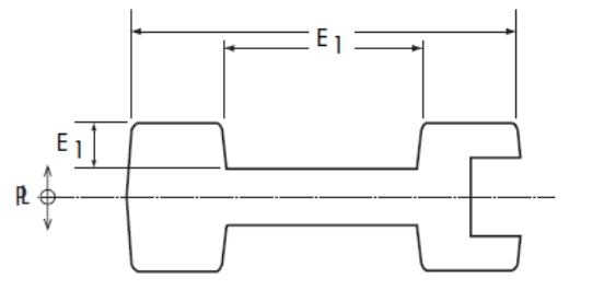
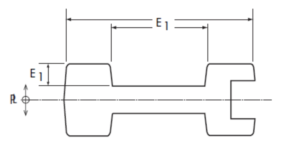
| Length of Dimension”E’ | Zinc | Aluminum | Mognesium | Copper |
| Basic Tolerance up to l”(25.4mm) | ±0.010 (±0.25mm) | ±0.010 (±0.25mm) | ±0.010 (±0.25mm) | ±0.014 (±0.36mm) |
| Addifional Tolerance foreach additiona inch over 1″(25.4mm) | ±0.001 (±0.025mm) | ±0.001 (±0.025mm) | ±0.001 (±0.025mm) | ±0.003 (±0.076mm) |
Note: Beczuse dies tuear over tbe course of producing casting,it should be noted that tbe mumber of sbots on a die prior to repair or replacement will belesfor tighter casting tolerances and greaterfor oider castin olerances.
Linear Dimensions: Precision Tolerances
| Table P-4A-1 Tolerances for Linear Dimensions(Precision) In inches,threeplace decimals (.xox);In milimeters,twoplace decimals(xx) | ||||
| Casting Alloys | ||||
| Length of Dimension “E₁” | Zinc | Aluminum | Magnesium | Copper |
| Basic Tolerance up to i”(25.4mm) | ±0.002 (±0.05mm) | ±0.002 (±0.05mm) | ±0.002 (±0.05mm) | ±0.007 (±0. 18mm) |
| Addifional Tolerance for each addifional inch over 1″(25.4mm) | ±0.001 (±0.025mm) | ±0.001 (±0.025mm) | ±0.001 (±0.025mm) | ±0.002 (±0.05mm) |
Note:Because dies zwear over the course of producing castings,it should be noted that the number of sbots on a die prior to repair or replacement zoill be lessfor tighter casting tolerances and greater for wider casting tolerances.
Parting Line: Standard Tolerances
Parting Line Tolerance is the maximum amount of die separation allowed for the end product to meet specified requirements of form, fit and function. This is not to be confused with Parting Line Shift Tolerance which is the maximum amount die halves shift from side to side in relation to one another.Parting Line Tolerance is a function of the surface area of the die from which material can flow from one die half to the other.
This is also known as Projected Area.Projected Area is always a plus tolerance since a completely closed die has 0 separation. Excess material and pressure will force the die to open along the parting line plane creating an oversize condition. The excess material will cause the part to be thicker than the ideal specification and that is why Projected Area only has plus tolerance. It is important to understand that Table S-4A-2 (Projected Area Tolerance) does not provide Parting Line Tolerance by itself. Part thickness or depth must be factored in to give a true idea of Parting Line Tolerance. Parting Line Tolerance is a function of part thickness perpendicular to the Projected Area plus the Projected Area Tolerance.
Example: An aluminum die casting has 75 in2 (483.9 cm2) of Projected Area on the parting die plane.From table S-4A-2, Projected Area Tolerance is +0.012. This is combined with the total part thickness tolerance from table S-4A-1 to obtain the Parting Line Tolerance.
The total part thickness including both die halves is 5.00 in. (127 mm) which is measured per pendicular to the parting die plane (dimension “E2 E1”). From table S-4A-1, the Linear Tolerance is ± 0.010 for the first inch and ±0.001 for each of the four additional inches. The Linear Tolerance of 0.014 inches is combined with the Projected Area Tolerance of +0.012 to yield a Standard Parting Line Tolerance of +0.026/-0.014 in. or in metric terms ±0.35 mm from Linear Tolerance table S-4A-1 plus+0.30 mm from Projected Area Tolerance table S-4A-2 = +0.65/-0.35 mm.
| Table S-4A-2 Parting Line Tolerances(Standard)-Added to Linear Tolerances | ||||
| Projected Area of Die Casting inches²(cm² | Casting Alloys Tolerances shown are plus”values onb) | |||
| Zinc | Aluminum | Magnesium | Copper | |
| up to 10 jn² (64.5cm²) | +0.0045 (+0.114 mm) | +0.0055 (+0.14 mm) | +0.0055 (+0.14mm) | +0.008 (+0.20mm) |
| 11in²to 20 in² 71.0 cm²to 129.0cm²) | +0.005 (+0.13mm) | +0.0065 (+0.165mm) | +0.0065 (+0.165mm) | +0.009 (+0.23mm) |
| 21in²to 50in² (135.5cm²to 322.6cm²) | +0.006 (+0.15mm) | +0.0075 (+0.19mm) | +0.0075 (+0.19mm) | +0.010 (+0.25mm) |
| 51in²to 100in² (329.0cm²to645.2cm²) | +0.009 (+0.23mm) | +0.012 (+0.30 mm) | +0.012 (+0.30mm) | 一 |
| 101in²to 200in² (651.6cm²to 1290.3 cm²) | +0.012 (+0.30 mm) | +0.018 (+0.46mm) | +0.018 (+0.46mm) | 一 |
| 201in²to 300 in² (1296.8 cm²to 1935.5cm²) | +0.018 (+0.46mm) | +0.024 (+0.61mm) | +0.024 (+0.61mm) | 一 |
For projected area of die casting over 300in2(1935.5cm²), consult with your die coster.
NADCA Product Specification Standards for Die Castings/2012
Parting Line Shift: Standard Tolerance
Example: Parting Line Shift Tolerance
The cavity area at the parting line is 75 inches squared. From Table S-4A-6, the Projected Area Parting Line Shift Tolerance is ± 0.006 (±0,152 mm). This is added to the Linear Tolerance from table S/P-4A-1.
| Table S-4A-6:Parting Line Shift Tolerance(Excluding unit dies) | |
| Projected Area of Die Casting inches ²(cm ²) | Additional Tolerance inches(mm) |
| up to 50 in ² | ±.004 |
| (322.6cm ²) | (±.102 mm) |
| 51 in²to 100 in ² | ±.006 |
| (329.0cm²to 645.2 cm ²) | (±.152 mm) |
| 101 in²to 200 in² | ±.008 |
| (651.6cm²to 1290.3 cm 2) | (±.203 mm) |
| 201 in²to 300 in ² | ±.011 |
| (1296.8cm²to 1935.5 cm ²) | (±.279 mm) |
| 301 in²to 500 in² | ±.016 |
| (1941.9cm²to 3225.8 cm 2) | (±.406mm) |
| 501 in²to 800 in ² | ±.020 |
| (3232.3cm²to 5161.3 cm ²) | (±.508mm) |
| 801in²to 1200 in² | ±.025 |
| (5167.7 cm²to 7741.9 cm ²) | (±.635 mm) |
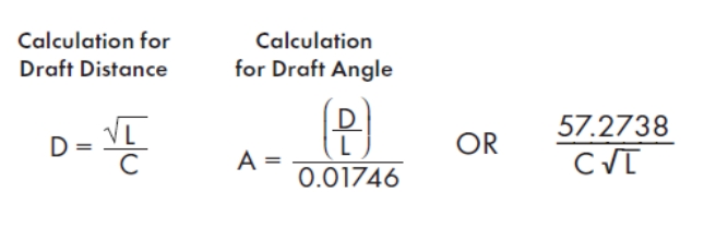
Draft Requirements: Standard Tolerances
In the case of an inside surface for an aluminum cast part, for which the constant “C” is 30 (6 mm), the recommended Standard Draft at three depths is:
| Depth | Draft Disfance | Draft Angle |
| in. (mm) | in. (mm) | Degrees |
| 0.1 (2.50) | 0.010(0.250) | 6° |
| 1.0(25) | 0.033(0.840) | 1.9° |
| 5.0(127) | 0.075(1.890) | 0.85° |
To achieve lesser draft than normal production allows,Precision Tolerances maybe specified(see opposite page).
Where:
D= Draft in inches
L= Depth or height of feature from the parting line
C=Constant, from table S-4A-7, isbased on the type offeatureand the die casting alloy
A= Draft angle in degrees Draft
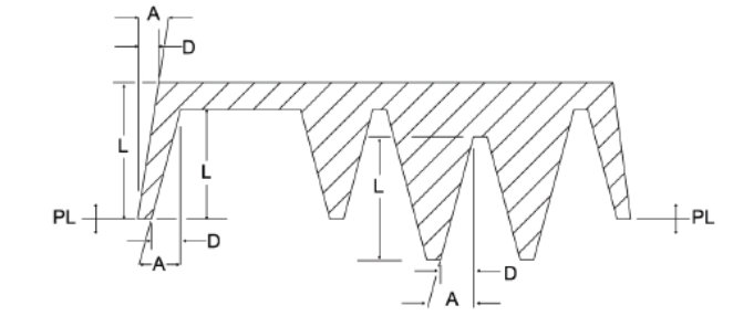
Drawing defines draft dimensions for interior and exterior surfaces and total draft for holes (draft is exaggerated for illustration).
Draft Requirements:Standard Tolerances
Table S-4A-7: Draft Constants for Calculating Draft and Draft Angle.
| Values of Constant “C”by Features and Depth (Standard Tolerances) | |||
| Alloy | Inside Wall For Dim.i inches (mm) | Outside Wall For Dim.in inches (mm) | Hole,Total Draft for Dim.in inches (mm) |
| Zinc/ZA | 50(9.90mm) | 100(19.80 mm) | 34(6.75mm) |
| Aluminum | 30 (6.00 mm) | 60(12.00 mm) | 20(4.68 mm) |
| Magnesium | 35 (7.00 mm) | 70 (14.00 mm) | 24(4.76 mm) |
| Copper | 25(4.90 mm) | 50 (9.90 mm) | 17 (3.33 mm) |
Cored Holes for Cut Threads: Standard Tolerances
Cored holes for cut threads are cast holes that require threads to be cut (tapped) into the metal. The table below provides the dimensional tolerances for diameter, depth and draft for each specified thread type (Unified and Metric Series). When required, cored holes in Al, Mg, Zn and ZA may be tapped without removing draft. This Standard Tolerance recommendation is based on allowing 85% of full thread depth at the bottom D2 (small end) of the cored hole and 55% at the top D1 (large end) of the cored hole. A countersink or radius is also recommended at the top of the cored hole. This provides relief for any displaced material and can also serve to strengthen the core.
Threads extend through the cored hole as by Y. X shows the actual hole depth. As with the countersink at the top of the hole, the extra hole length provides relief for displaced material and allows for full thread engagement. Tolerances below apply to all alloys.
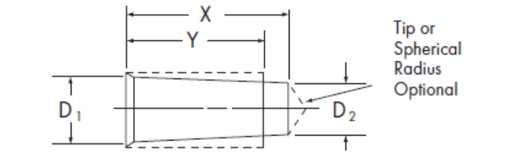
Table S-4A-9: Cored Holes for Cut Threads (Standard Tolerances) – Unified Series and Metric Series.
| Unified Series/Class | Hole Diameter D₁.Max.D2 ,Min. inches inches | Thread Depth Y,Max. inches | Hole Depth X,Max. inches | Metric Series Thread | Hole Diameter | Thread Depth Y,Max. mm | Hole Depth XMax. mm | |||
| D1,Max mm | D2 Min. mm | |||||||||
| Size A | ||||||||||
| 6-32,UNC/2B,3B | 0.120 | 0.108 | 0.414 | 0.508 | M3.5X0.6 | 3.168 | 2.923 | 7.88 | 9.68 | |
| 6-40,UNF/2B | 0.124 | 0.114 | 0.345 | 0.420 | M4X07 | 3.608 | 3.331 | 9.00 | 11.10 | |
| 8-32,UNC/2B | 0.146 | 0.134 | 0.492 | 0.586 | M5X0.8 | 4.549 | 4.239 | 11.25 | 13.65 | |
| 8-36,UNF/2B | 0.148 | 0.137 | 0.410 | 0.493 | M6X1 | 5.430 | 5.055 | 13.50 | 16.50 | |
| 10-24 UNC/2B | 0.166 | 0.151 | 0.570 | 0.695 | M8X1.25 | 7.281 | 6.825 | 18.00 | 21.75 | |
| 10-32,UNF/2B | 0.172 | 0.160 | 0.475 | 0.569 | FM8X1 | 7.430 | 7.055 | 14.00 | 17.00 | |
| 12-24 UNC/2B | 0.192 | 0.177 | 0.648 | 0.773 | M10X1.5 | 9.132 | 8.595 | 22.50 | 27.00 | |
| 12-28,UNF/2B | 0.196 | 0.182 | 0.540 | 0.647 | FM10X0.75 | 9.578 | 9.285 | 10.00 | 12.25 | |
| 1/4A-20,UNC/1B,2B | 0.221 | 0.203 | 0.750 | 0.900 | fM10X1.25 | 9.281 | 8.825 | 20.00 | 23.75 | |
| 1/4A-28,UNF/1B,2B | 0.230 | 0.216 | 0.500 | 0.607 | M12X175 | 10.983 | 10.365 | 27.00 | 32.25 | |
| 5/16-18,UNC/1B,2B | 0.280 | 0.260 | 0.781 | 0.948 | fM12X1 | 11.430 | 11.055 | 15.00 | 18.00 | |
| 5/16-24,UNF/1B,2B | 0.289 | 0.273 | 0.625 | 0.750 | FM12X1.25 | 11.281 | 10.825 | 18.00 | 21.75 | |
| 3/8-16,UNC/1B,2B | 0.339 | 0.316 | 0.938 | 1.125 | M14X2 | 12.834 | 12.135 | 31.50 | 37.50 | |
| 3/8-24,UNF/1B,2B | 0.351 | 0.336 | 0.656 | 0.781 | FM14X1.5 | 13.132 | 12.595 | 24.50 | 29.00 | |
| 7/16-14,UNC/1B,2B | 0.396 | 0.371 | 1.094 | 1.308 | 14.430 | 14.055 | 15.00 | 18.00 | ||
| 7/16-20,UNF/1B,2B | 0.409 | 0.390 | 0.766 | 0.916 | M16×2 | 14.834 | 14.135 | 32.00 | 38.00 | |
| 1/2-13,UNC/1B,2B | 0.455 | 0.428 | 1.250 | 1.481 | 15.132 | 14.595 | 24.00 | 28.50 | ||
| 1/2-20,UNF/1B,2B | 0.471 | 0.453 | 0.750 | 0.900 | FMI6×15 | 16.430 | 16.055 | 15.30 | 18.30 | |
| 9/16-12,UNC/1B,2B | 0.514 | 0.485 | 1.406 | 1.656 | fM18X1.5 | 17.132 | 16.595 | 24.30 | 28.80 | |
| 9/16-18,UNF/1B,2B | 0.530 | 0.510 | 0.844 | 1.010 | M20X2.5 | 18.537 | 17.675 | 40.00 | 47.50 | |
| 5/8-11,UNC/1B,2B | 0.572 | 0.540 | 1.563 | 1.835 | 19.430 | 19.055 | 15.00 | 18.00 | ||
| 5/8-18,UNF/1B,2B | 0.593 | 0.573 | 0.781 | 0.948 | FM20×15 | 19.132 | 18.595 | 25.00 | 29.50 | |
| 3/4A-10,UNC/1B,2B | 0.691 | 0.657 | 1.688 | 1.988 | fM22X1.5 | 21.132 | 20.595 | 25.30 | 29.80 | |
| 3/4A-16,UNF/1B,2B | 0.714 | 0.691 | 0.938 | 1.125 | M24X3 | 22.239 | 21.215 | 48.00 | 57.00 | |
| 7/8-9,UNC/1B,2B | 0.810 | 0.772 | 1.750 | 2.083 | fM24X2 | 22.834 | 22.135 | 30.00 | 36.00 | |
| 7/8-14,UNF/1B,2B | 0.833 | 0.808 | 1.094 | 1.308 | FM25X1.5 | 24.132 | 23.595 | 25.00 | 29.50 | |
| 1-8,UNC/1B,2B | 0.927 | 0.884 | 2.000 | 2.375 | fM27×2 | 25.834 | 25.135 | 3375 | 39.75 | |
| 1-12,UNF/1B.2B | 0.951 | 0.922 | 1.250 | 1.500 | M30X3.5 | 27.941 | 26.754 | 60.00 | 70.50 | |
f= Fine Pitch Series
Additional Considerations for Large Castings
1 Fillet Radii:
1.1: Definition: Wall thickness is the distance between two parallel or nearly parallel surfaces. Wall thickness may vary depending on the application of draft. Wall thickness should be maintained as uniform as possible. A general guideline would be to keep the range of thickness within 2X of the thinnest wall. A second guideline is to keep the wall as thin as possible to meet the castings functional requirements.
1.2: General: 0.14” (3.5mm (+/- 0.5mm)1.2.1 Deviations: from the nominal condition are based upon product function and manufacturing process requirements.
2 Radii:
2.1 Fillet Radii: 2.1.1 General: 0.14” (+0.08/-0.04”) [3.5mm (+2.0mm/-1.0mm)]
2.1.1.1 Deviations: from the nominal condition are based upon product function and manufacturing process requirements.
2.1.2 Minimum: 0.060” (1.5mm)
2.2 Corner Radii:2.2.1 General: 0.060” (+0.08/-0.04”) [1.5mm (+2mm/-1mm)]
2.2.1.1 Deviations: from the nominal condition are based upon product function and manufacturing process requirements.
2.2.2 Minimum: 0.020” (0.5mm)
3 Cores:
3.1 Guidelines: Cores should be used to minimize machining stock, and should be pulled perpendicular to each other. Use stepped cores where possible to minimize finish stock, reduce heavy sections, and minimize porosity.
3.2 Minimum: Cored hole diameter to be 0.25” (6.0mm) in and parallel to the direction of die draw.
3.3 For holes Less Than: 0.50” (12.5mm) diameter the core hole length to diameter (L/D) ratio should not exceed 4:1.
3.4 For Holes Greater Than: 0.50” (12.5mm) diameter the core pin length to diameter (L/D) ratio should not exceed 10:1
Ejector Pin Bosses:
Surface Geometry:6.2.1: 0.06” (1.5mm) raised to 0.03” (0.8mm) depressed.
7 Trimming & Cleaning:
7.1 Parting Lines:
7.1.1 Trim Ribs-Gate and Parting Line: 0.12” maximum (1.5mm)
7.1.2 Gates & Overflows: 0-0.059” (0-1.5mm)
7.1.3 Flash: Asspecified in normal standard.
7.2 Cored Holes: 0-0.02” (0-0.5mm)
7.3 Openings:
7.3.1: 0-0.06” (0-1.5mm) at the finish machined face
7.3.2: 0-0.03”(0-0.8mm) on as-cast surfaces
7.3.3: 0-0.01” (0-2.5mm) of corner radii
7.4 Corners – Sharp: Not removed.
7.5 Ejector Pin Flash (Max. Projection):
7.5.1: 0-0.12” (0-3.0mm) on machined surfaces.
7.5.2: 0-0.04” (0-1.0mm) on as-cast surfaces.
7.6 Machined Surfaces: 0.12” (0-0.3mm) max.
7.7 Seam Lines: 0-0.02” (0-0.5mm)
7.8 Negative trim (shearing): condition is allowed when the nominal wall thickness is maintained.
Engineering & Design: Additional Specification Guidelines
Acceptable Ejector Pin Marks
Ejector pin marks on most die castings may be raised or depressed .015” (.381 mm). Raised ejector pin marks are preferred for optimum production. Larger castings may require additional ejector pin tolerances for proper casting ejection.
Ejector Pin Flash
Ejector pin marks are surrounded by a flash of metal. Normally, ejector pin flash will not be removed, unless it is objectionable to the end use of the part.Alternatively, ejector pin flash may be specified as crushed or flattened.In the case of either nonremoval or crushing/flattening, flash may flake off in use.Complete removal of ejector pin marks and flash by machining or hand scraping operations should be specified only when requirements justify the added expense.
With each die casting cycle, the die opens and the ejector plate in the ejector half of the die (Fig. A) automatically moves all ejector pins forward (Fig. B), releasing the casting from the die. Then, the die casting is removed from the die manually or mechanically.
5 Metal Extension (Flash) Removal
Guidelines to Extent of Removal
The table below provides a guide to the types of die casting metal extension (flash) which occurs in typical die castings and the amount of metal extension material which remains after (1) degating (removal of any gates and runners from the casting), and (2)commercial trimming of die casting metal extension.
Note that in some instances, where special surface finish characteristics are not involved, the most economic method of degating and metal extension (flash) removal may include a tumbling or vibratory deburring operation.
| Guide to Nominal Metal Remaining by Type of Extension | |||||
| Type of Metal Extension and Nominal Amount Remaining After Degating and Trimming | |||||
| Operation Description | Thick Gates & Overflows >0.12”(3.0 mm) | Thin Gates & Overflows ≤0.12”(3.0 mm) | Parting Line and Seam Line Metal Extension | Metal Extension in Cored Holes | Sharp Corners |
| After Degating Nominal Flash Remaining | Rough within 0.12”(3.0 mm) | Rough within 0.12”(3.0 mm) | Excess Only Broken Off | Not Removed | Not Removed |
| After Commercial Trimming* Nominal Extension Emaining | Within 0.06”(1.59mm) | Within 0.03”(0.8mm) | Within 0.015”(0.38 mm) | Removed within 0.010”(0.25 mm) | Not Removed |
| *“Commercially trimmed”does not include additional operations to remove loose material.For very beavy gates and overflowus,consultyour die caster. | |||||
Surface Finish, As-Cast
General Guidelines for As Cast Surface Finish on Die Cast Parts
The specification of external surface finish requirements is desirable for selected die casting applications and, in the case of some decorative parts, essential.The purpose of the guidelines presented here is to classify as-cast surface finish for die castings into a series of grades so that the type of as-cast finish required may be addressed and defined in advance of die design.These guidelines should be used for general type classification only, with final surface finish quality requirements specifically agreed upon between the die caster and the customer.The first four classes listed relate to cosmetic surfaces. Classfive relates to selected surface areas where specified surface finish limitations are required.
| As-Cast Surface Finish Classifications and Final Finish or End Use | |||
| Class | As-Cast Finish | Final Finish or End Use | |
| 1 | Utility Grade | No cosmetic requirements.Surface imperfections (cold shut,rubs,surface porosity,lubricant build-up,etc.)are acceptable | Used as-cast or with protective coatings; Anodize(non-decorative) Chromate(yellow,clear) |
| 2 | Functional Grade | Surface imperfections(cold shut,rubs, surface porosity,etc.),that can be removed by spot polishing or can be covered by heavy paint,are acceptable. | Decorative Coatings: Lacquers Enamels Plating(A1) Chemical Finish Polished Finish |
| 3 | Commercial Grade | Slight surface imperfections that can be removed by agreed upon means are acceptable. | Structural Parts (high stress areas) Plating(Zn) Electrostatic Painting Transparent Paints |
| 4 | Consumer Grade | No objectionable surface imperfec- tions.Where surface waviness (flatness), noted by light reflection,is a reason for rejection special agreement should be reached with the die caster. | Special Decorative Parts |
| 5 | Superior Grade | Surface finish,applicable to limited areas of the casting and dependent on alloy selected,to have a maximum value in micro inches as specified on print. | O-Ring Seats or Gasket Areas |
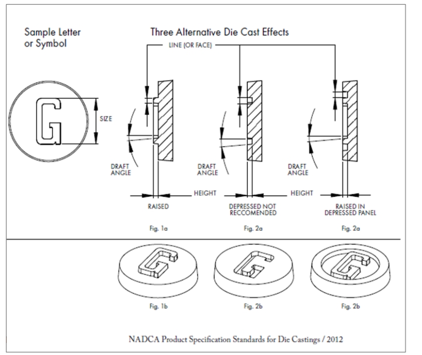
7 Die Cast Lettering and Ornamentation
Lettering, medallions, logotypes, trademarks and a range of identification symbols may be reproduced on the surfaces of die cast parts.
Such as-cast ornamentation may be raised or depressed, but note that raised lettering will result in lower die construction costs and reduced die maintenance over the life of the die.Raised lettering on a depressed panel can be an economical substitute for depressed letters, as shown in the illustration below
Cast-in Lettering/Ornamentation Guidelines
In addition to the avoidance of depressed lettering or symbols in the casting surface,the following guidelines will achieve the most satisfactory results. The terms used refer to the illustrations below.
1. The Line Thickness (or “face”) of any letter to be clearly cast should be 0.010 in. (0.254 mm) or greater.
2. The Height (or raised dimension) of a cast letter or symbol should be equal to or less than the line thickness.
3. The Draft Angle should be greater than 10。.
4. Letters or symbols containing fine serifs or delicate lines cannot be expected to die cast cleanly.