Design tips for plastic parts

Posted on : February 16, 2022 By GREFEE
Plastics: main composition of plastics are carbon, oxygen, hydrogen, nitrogen and other organic or inorganic elements. They’re solid but can be molten liquids in the manufacturing process. Melting by heating, flowing by pressure, and solidified by cooling make the materials present various shapes, such large numbers and changeful material group are called plastics.
Characteristics of plastic materials:
- Low intensity and low toughness.
- Abundant raw materials, low cost.
- Easy-molding, easy to achieve complicated shapes, can achieve mass production.
- Light weight, low density(the proportion of plastic is 0.9~2, aluminum 2.7, iron 7.8).
- Continuous distortion occurs easily under the action of external forces.
- Bright colors, easy to tint, can change color by properly adding coloring agent
- Good property of insulating
- Good properties in resisting corrosion, water, oil, acid, chemical and rust.
- Poor heat resistance, the heat resistance temperature of most plastics is below 150 ℃
- Non-electrical and thermal conductivity.
- May have other special properties, such as transparency, elasticity, etc.
Classification of plastic:
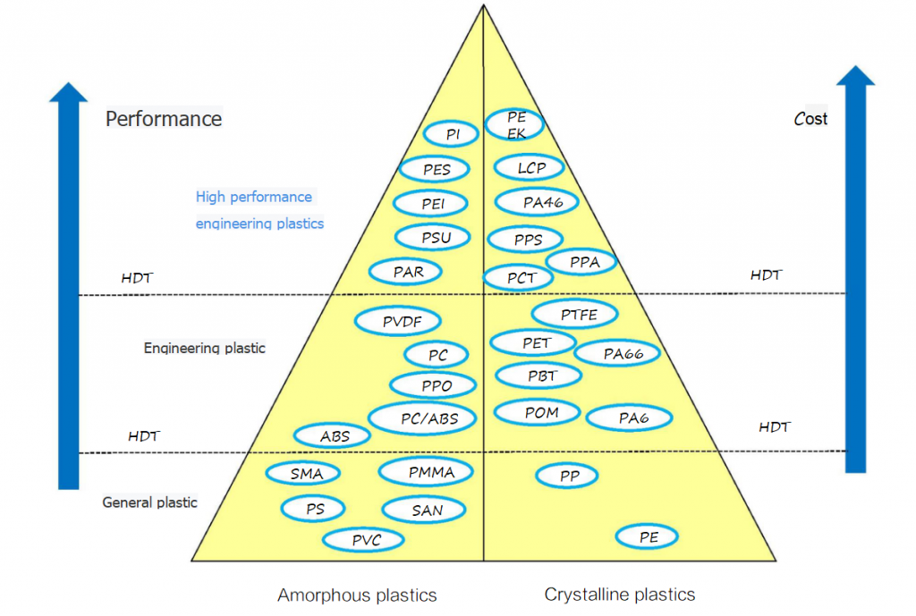
Material options
- Physical properties data
- Functional requirements of part
- Requirements on working environment
- Price
- Assembling requirements
- Dimensional stability
- Appearance
- Safety requirements
Wall thickness of plastic parts
A . the wall thickness of parts must be appropriate
◮ Too thin wall thickness :
Low strength;
Great flow resistance, insufficient filling of molten materials
◮ Too thick wall thickness:
Parts have quality problems such as shrinkage, holes and warping
Parts require longer cooling time and lead time, but have low productivity
Parts require more material, which increases the cost of parts.
◮ Suitable wall thickness range for common plastic materials(Unit: mm):
| PE | PP | Nylon | PS | AS | PMMA | PVC | PC | ABS | POM | |
| maximum | 0.9 | 0.6 | 0.6 | 1.0 | 1.0 | 1.5 | 1.5 | 1.5 | 1.5 | 1.5 |
| minimum | 4.0 | 3.5 | 3.0 | 4.0 | 4.0 | 5.0 | 5.0 | 5.0 | 4.5 | 5.0 |
B.Try to decrease the wall thickness of the parts as much as possible
Factors determining the wall thickness of
- Strength requirements on parts
- Whether the part can resist demolding force in molding
- The part can resist fastening force in assembling
- When there’s metal insert, whether the strength around the insert is enough
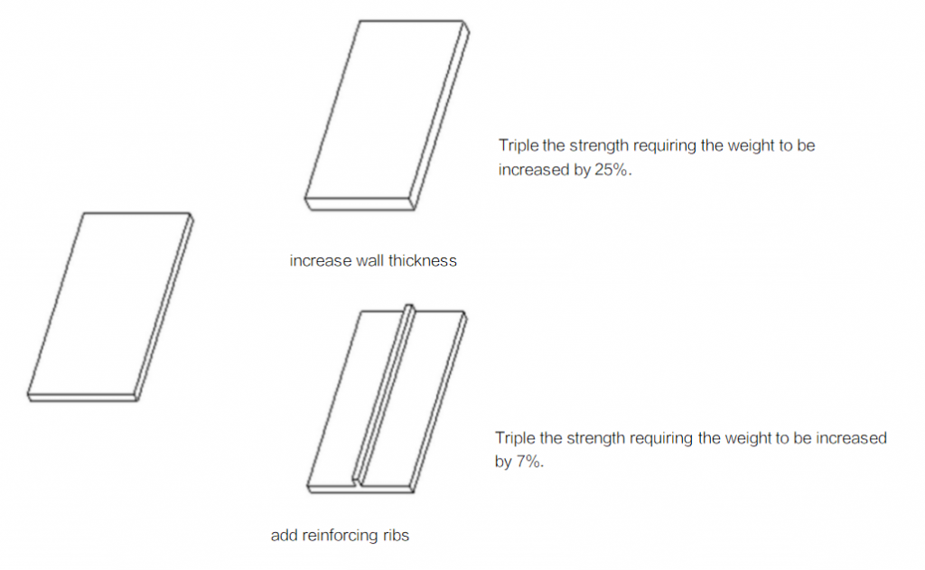
Incorrect practices: increase the wall thickness blindly to improve the strength of parts.
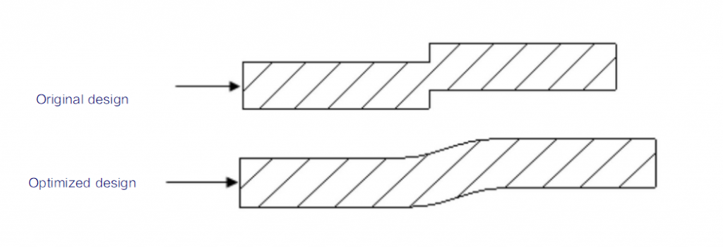
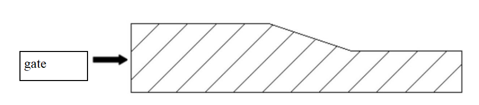
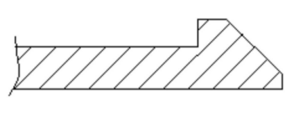
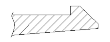
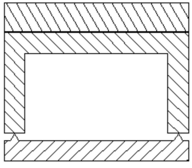
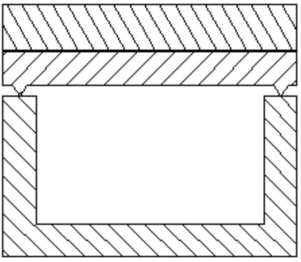
C.Even part wall thickness
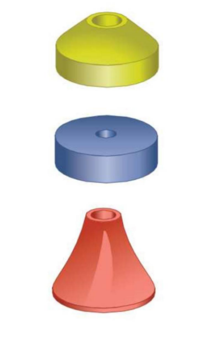
when the wall thickness is

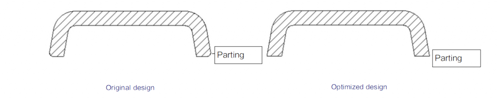
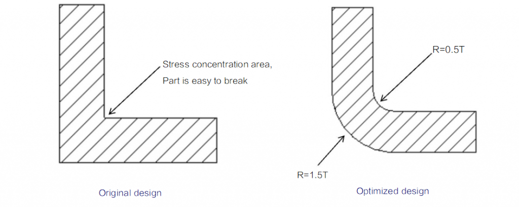
Avoid sharp corners
Avoid sharp corners outside

Exception: it’s better to design right angle at the areas around the parting lines of the part
Avoid sharp corners along the flow direction of the molten
Avoid sharp corners around joint areas of the
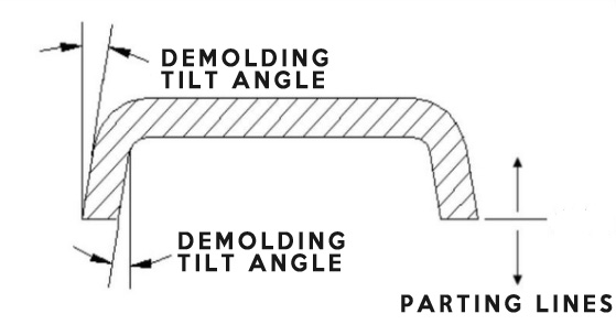
Demolding draft
Factors determining the demolding
- Demolding draft is generally
- Plastics with large shrinkage require larger demolding draft.
- Design small demolding draft for features requiring high dimensional accuracy.
- Make the demolding slope of male die less than female die to facilitate demolding
- Design relatively larger demolding slop when part has thick wall thickness and large
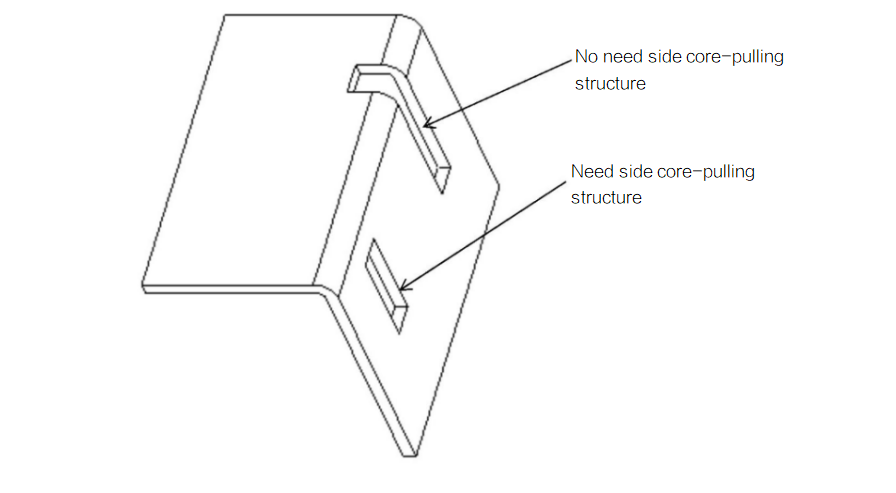
- Some planes on parts with functional requirements can be designed without demolding draft, but need design side core-pulling structure on mold, in this case, mold has complex structure and high cost.
- Try to make the demolding draft as large as possible without affecting the parts’ appearance and functions.
The size and direction of demolding draft should not affect the parts’ function.

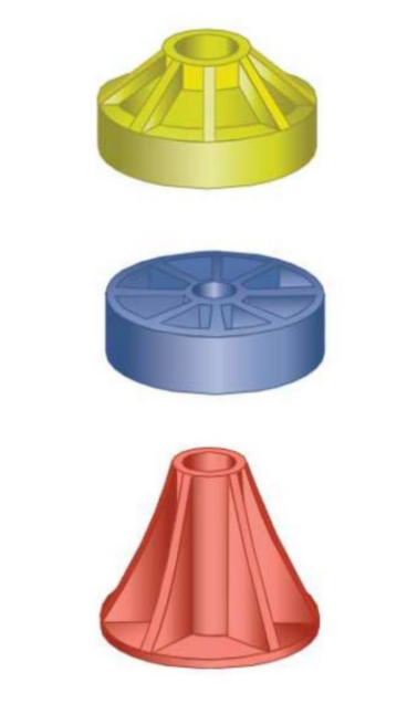
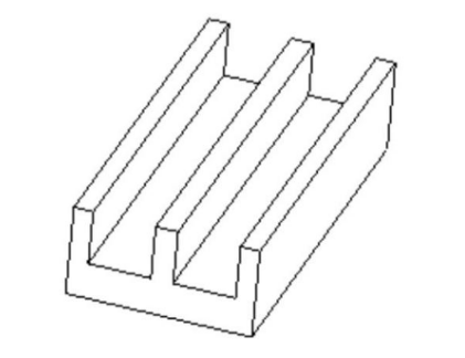
Design of reinforcing ribs
- Reinforcing rib size.
- rib thickness
- rib height
- rib root radius
- demolding draft for rib
- space

Design principles of reinforcing ribs
even wall thickness


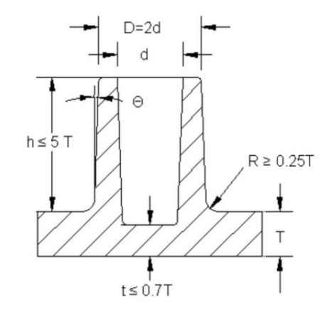
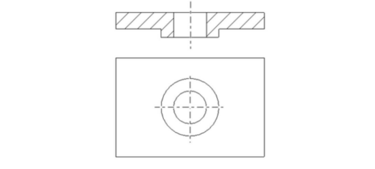
Design of supporting pillars
- pillar size
- OD & ID of pillars:
- thickness of
- height of
- root radius of pillars:
- root thickness of pillars:
- demolding draft of pillars:
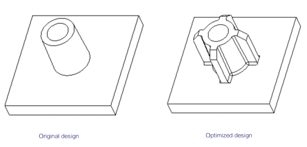
Design principles of supporting ribs
even wall thickness
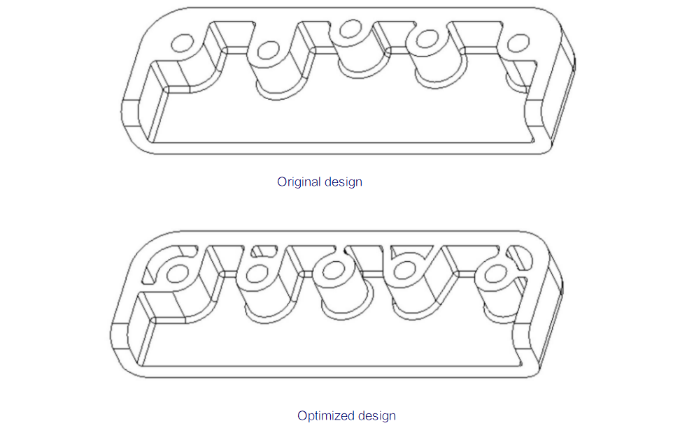
connecting with the part wall

Adding reinforcing ribs around the single supporting rib:
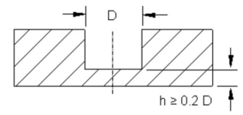
Design of holes:
The size for hole depth:
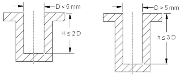
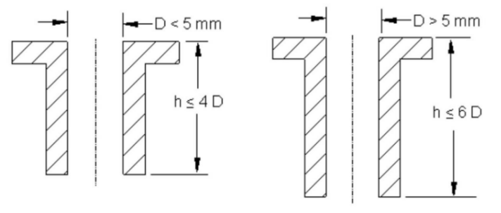
The size for spacing between holes and the edge size between holes and parts:

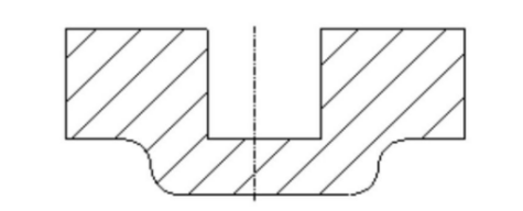
avoid too thin thickness around the root of the blind holes
the holes on the part should be as far away from the loading part as possible
increase flange around hole edges and increase the strength of the holes
Avoid side holes perpendicular to the demolding direction of the part:
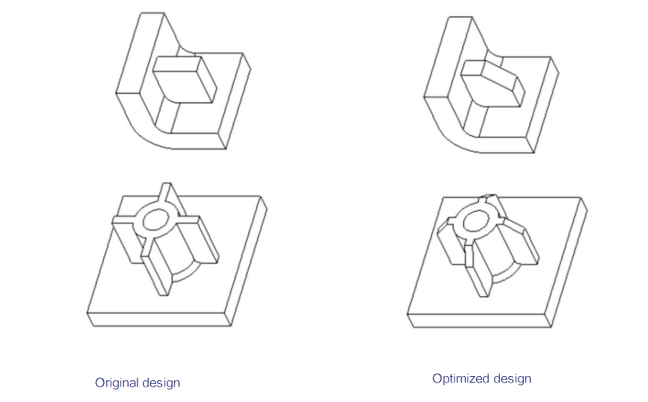
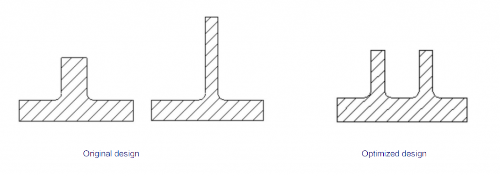
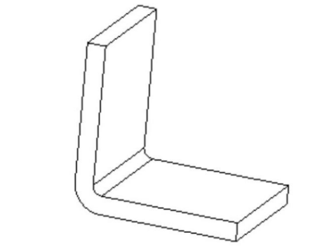
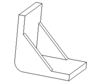
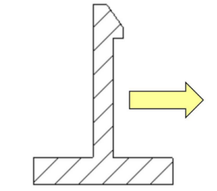
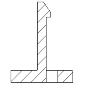
Design of improving the strength of plastic parts
Increase part strength byRaising the part strength with more reinforcing ribs rather than lifting wall thickness:
Should take the loading direction into consideration for the direction of reinforcing ribs:
Multiple reinforcing ribs are better than single thicker or taller reinforcing ribs:
Design part with strengthened


E.Add side walls

F.Avoid stress concentration on parts
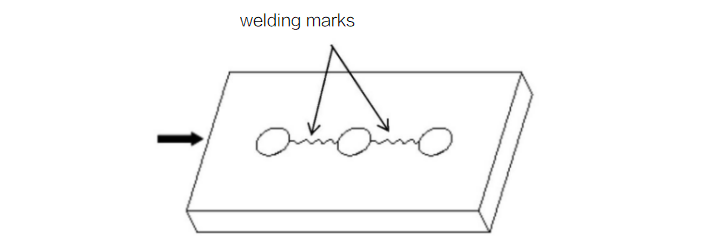
G.Avoid part bearing load around welding marks area

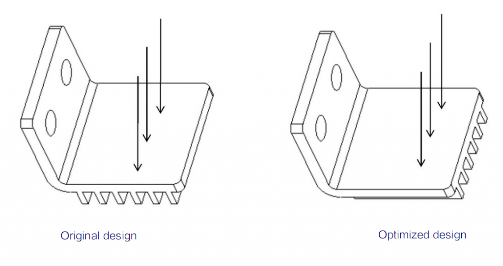
H.Optimized design:
One way to improve the strength of plastic parts is by replacing ordinary plastic materials with glass fiber reinforced plastics as it enhances the part strength which merely focuses on fiberglass.
Plastic parts have better ability of bearing compressive loading than stretching loading:
Avoid part bearing circular load. When the part bears circular loading, such as areas around metal inserts, it’s easy to crack then cannot work.
When the part is under impacting loading, the integrity of the part profile is essential and also no gaps and stress concentration are allowed on the part profile in the direction of impaction loading.
Design for improving the appearance of plastic parts
- Choose proper plastic.
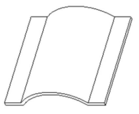
- Avoid shrinkage on part surfaces.
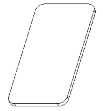
- Avoid part distortion.
- Design artistic grooves.
- Avoid welding marks on the part surface.
- Avoid steps or burrs on part.
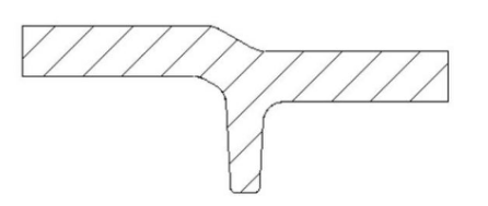
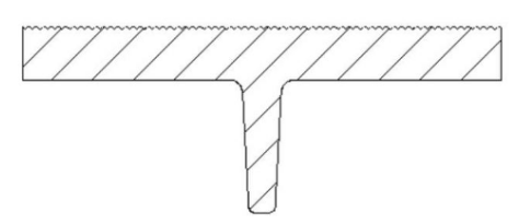
hiding shrinkage marks by designing:


proper gate:

avoid part distortion:

Design artistic grooves
Avoid welding marks on the part surface:
Adding textures on plastic part surface can cover some welding marks, but cannot completely cover. Painting can cover the welding marks.
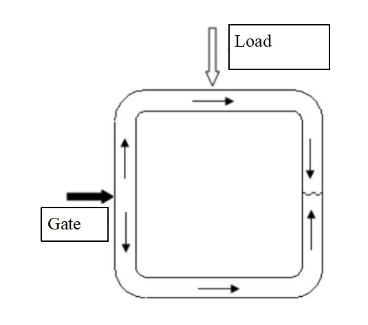
Properly design the gate locations and quantities, to avoid welding marks on important surfaces of the part and ensure smooth ventilation.
Design for lowering the cost of the plastic parts:
A.Design multi-functional parts:
B.lower the cost of part material
Decrease the thickness of the part
improve part strength by adding reinforcing ribs instead of increasing wall thickness.
remove material in thick areas of the part.
C.Simplify the part design and lower down the cost
KISS principle (Keep it simple, stupid),Simple is beauty!
Every feature in part must have a reason for its existence, otherwise, this feature can be removed.
D.Avoid strict tolerances of parts.
The tighter the tolerance, the higher the cost of manufacturing the part.
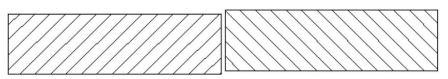
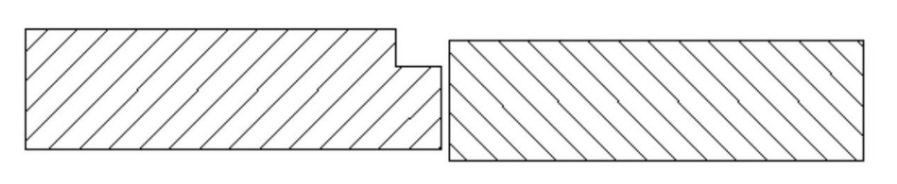
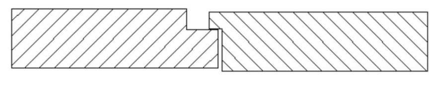
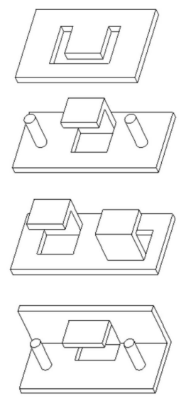
E.Avoid undercuts in part designing
Re-design parting lines to avoid some undercuts outside the part:


Re-design part features to avoid undercuts:

F.Lower down the modifying cost
injection feasibility design of the part
Reduce the times of part designing and modifying
Avoid the mold modification of adding materials
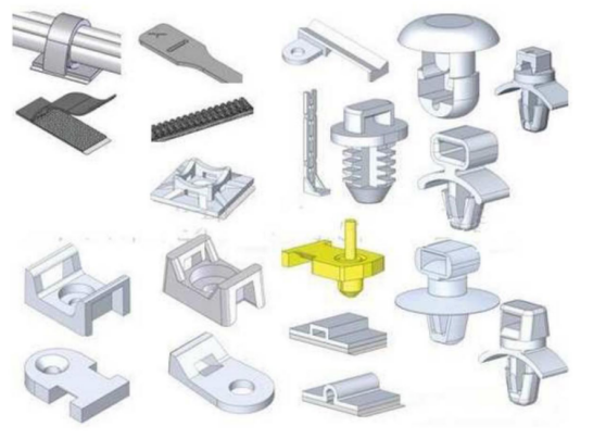
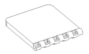
G.Adopt snap-fit to replace screws for fixing.
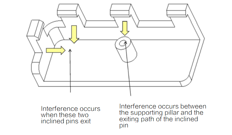
Feasibility design of injection mold
A.In snap-fit structure, should leave enough exiting space for inclined pins(or slides).
B.Avoid designs of thin iron and low strength in molds:

Assemble of plastic parts
Advantages and disadvantages of each assembling method:
| Advantages | Disadvantages | |
| Snap-fit | 1.Low cost 2.Removable 3.Flexible design 4. Assemble and remove quickly | 1. Clearance in snap-fit makes fixing unstable and noise 2.It can not be used for assembling with pre-load, and easy to creep under long-term stress 3. Not suit for application requiring frequently disassembly |
| Mechanical fastener | 1.Robust design 2. Repeating removable | 1.Plastic supporting pillars are easy to break under twisting force. 2. Loose tapping (self-tapping bolt) |
| Welding | 1. High strength 2.no creep problem | 1. secondary processing may increase the cost 2. non-removable 3. There’re poor welding performance between some plastics |
Design tips for snap-fit
Classification of snap-fits:


Size for snap-fit:
thickness of snap-fit t = 0.5~0.6T
Root round corner of snap-fit Rmin = 0.5t
Height of snap-fit: H = 5~10t
Height of snap-fit: H = 5~10t
Disassembling angle β:
β≈35° suits for removable assembling without external force
β≈45° suits for removable assembling requiring relatively smaller external force
β≈80°~90° suits for non-removable assembling requiring very large external force

Top thickness of snap-fit Y ≤ t
Add round corners around the root of

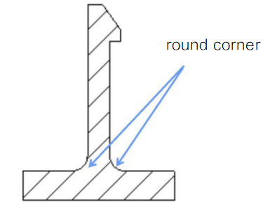
Optimized design
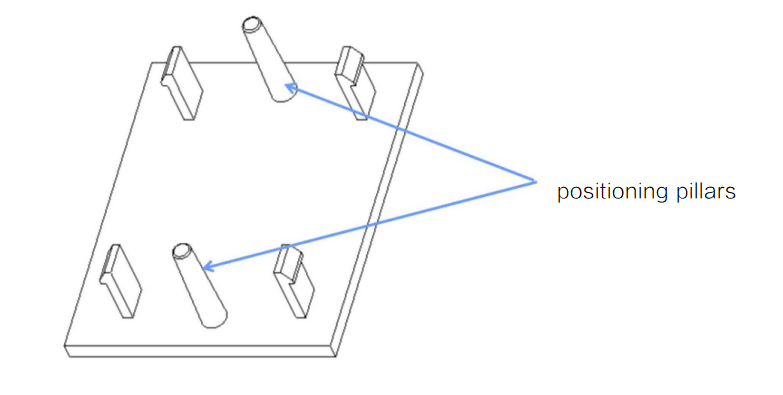
Snap-fits are evenly distributed
And are evenly arranged around the part to bear the load evenly
Add positioning pillars to assist snap-fitting and improve assembling accuracy
Consider the convenience of mold modification,Generally the size of snap-fit will be modified for many times, suggest set size in small firstly to ensure the convenience of modifying the mold
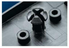
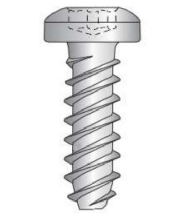
Mechanical fastening
Types of self-tapping bolts

Design notes for supporting pillars with self-tapping bolts
assembly times:generally assembly times should not more than 3 times
OD&ID of supporting:

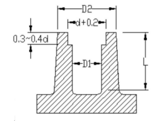
Design notes for supporting pillars with self-tapping bolts
The bite length of the thread should not be less than 2 times of the nominal diameter of the screw
the depth of supporting pillars is at least 0.5mm taller than the length of screws
add inclined angles or countersunk holes at the top of supporting pillars
Guiding role
Provide space for plastic shavings


Design notes for supporting pillars with self-tapping bolts
Add reinforcing ribs around supporting pillars, and add round corners around the root of supporting pillars.
Breaking is the most common failure of the supporting pillars.
Reasonable drive torque.
Too much driving torque will cause the crack of the supporting pillars
Ultrasonic welding

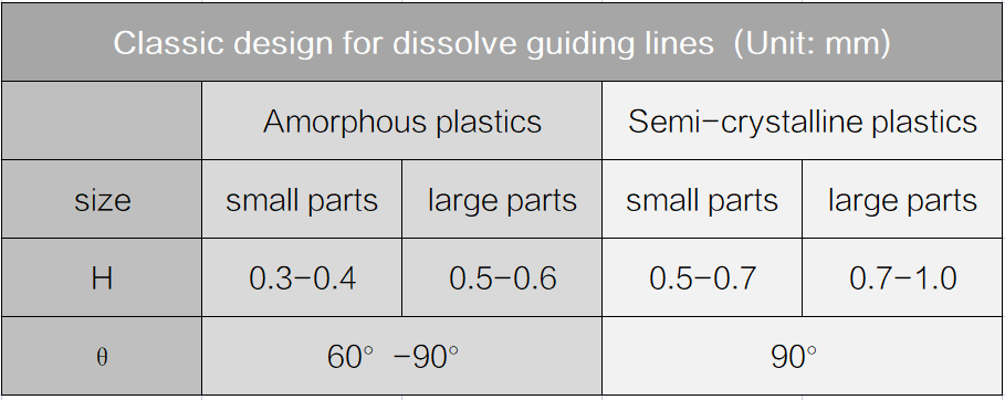
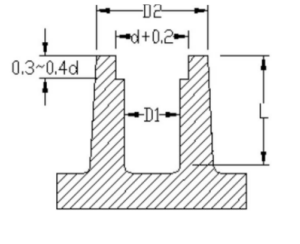
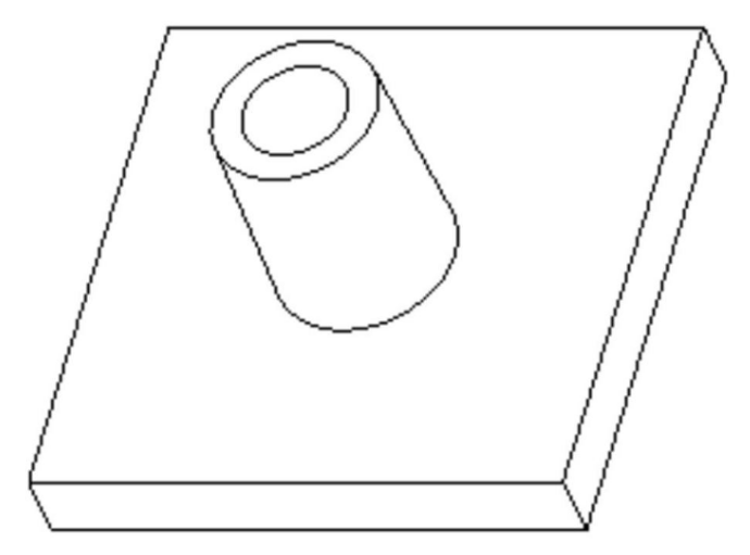
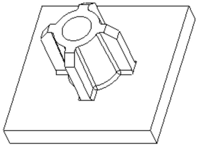
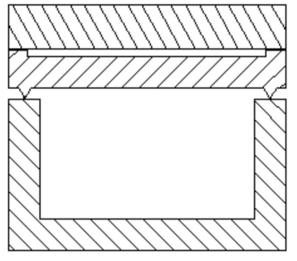
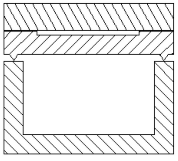
Design for dissolve guiding lines
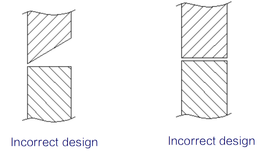
Design for welding
Design for Plastic parts
Proper design of dissolve guiding lines,Design locating features.
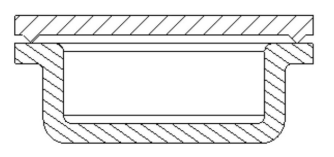


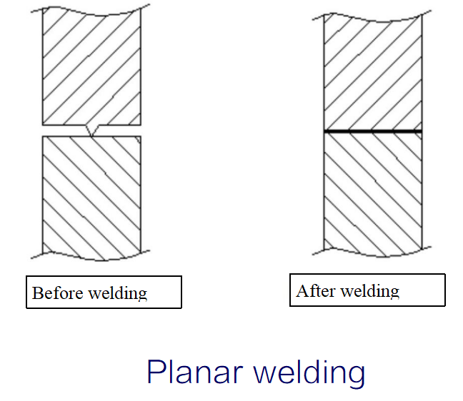
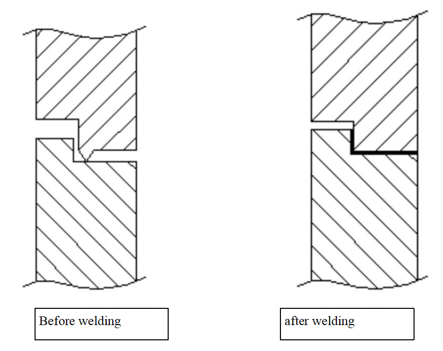
The welded surfaces are in the same plane,design for art grooves.
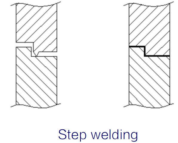
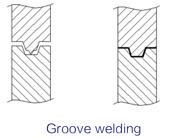
Increase the area between welding head and welding surface of plastic parts
Take the short-range welding as the first
MORE BOLG
Categories
Latest blog
- Compound Bow – Full-Process Technology Disassembly
- Consumer Electronics – CNC Machining Solutions for Photography Series Components
- Selection Logic of the Four Major Casting Processes
- Customization Case of Electrical Parts
- Precision Gear Machining – Precision Transmission, Driving the Future

Try GREFEE now,for free
We keep your uploaded files confidential and secure.