Considerations of the Sheet Metal Parts Design

Posted on : May 5, 2022 By GREFEE
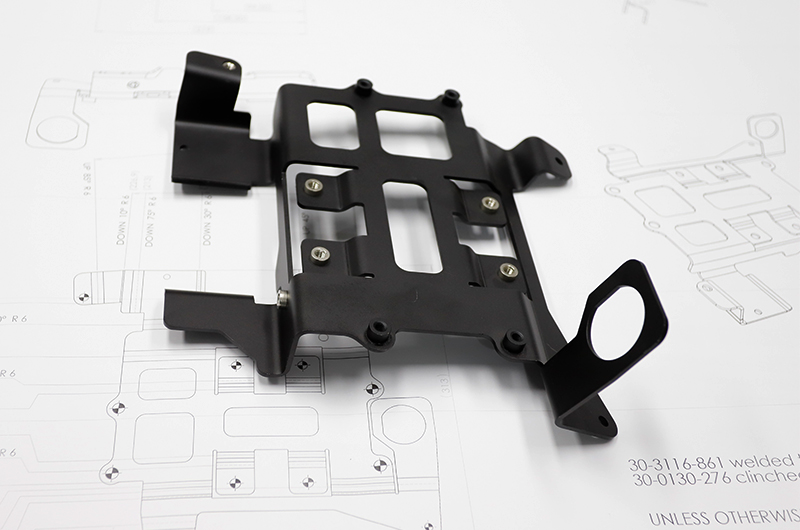
Sheet metal is widely used in industries like electronic appliances, telecommunication, automotive industry, and medical devices due to its lightweight, high strength, electric conductivity (can be used for EMC), low cost, excellent properties, and mass production. Sheet metal parts are an indispensable part of many products and can be found in computer cases, mechanical connectors, etc. Since many products contain sheet metal parts, their design and development process is quite essential. The mechanical engineers must grab the design skills of sheet metal parts to make them meet the needs of the appearance and function of products. It also lowers the cost of stamping molds and makes it easier for manufacturing. For more information, contact our experienced engineers!
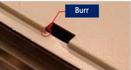
1. Mark the direction of burrs clearly
The sheet metal will have burrs when blanking and punching, especially if the mold is worn after a production stage, so the situation becomes worse or even could lead to finger injuries. Thus, in the drawing and mold-making processes, the directions of burrs must be marked clearly according to the function.
2. Hole spacing design & ventilation holes design
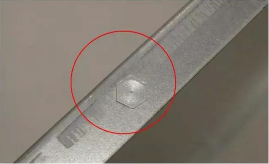
(1). The shortest distance between two adjacent holes is better, not less than 1.5 times that thickness of materials. Otherwise, it is easy to lead to cavity cracking and production interruption. Interruption and mold repairing are all factors of a high cost and low profit. If the distance between two holes must be necessarily less than 1.5 times that material thickness, tabs mode is used necessarily.
(2). The circular holes are the hardest and the easiest to produce and repair, but the opening rate is low.
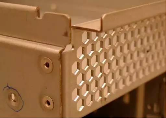
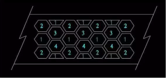
(3). The opening rate of the square holes in the highest. However, due to it being 90 degrees, the corners are likely to be collapsed and worn, which might need to repair the mold and stop the production lines. While the hexagonal honeycomb with an angle (120 degrees) is more strong than the square holes but is not as good enough as opening rates compared with square holes
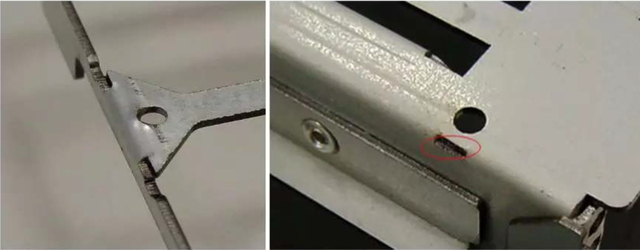
3. Distance between protrusion and bending edge
When bending the components, the components on the bottom margin, like studs or the internal protrusion, should not be close to the bending. The distance is better over 10mm. Otherwise, The corner below the projection has no male die to punch its R angle, which will be bigger than the R angle on two sides. The inconsistent R angle will affect its appearance. Processing methods: an indentation and appropriate length through stamping before bending, except for improving its appearance.
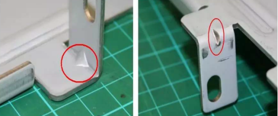
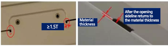
4. Distance between the holes and bending edges
The opening holes on the sidewalls should not be too close when bending, better higher than 3mm. Otherwise, the opening holes deform due to bending and dragging. Solutions: A length equivalent to the opening be punched out before bending, and the long strip hole has a width of 1.5 times of material thickness. It can cut off the drag without affecting the appearance of the opening holes.
5. Key points of screw hole design
Typically, the setscrew has three methods:
(1) stamping through holes on the sheet metal surface or drawing holes. Use the self-tapping screws. Among the self-tapping screws, the TAP TITE is optimal. Screwloose is unlikely to happen. Only the driven force will be heavier than the non-triangular self-tapping screws’.
3mm diameter screw lock matches 2.4~2.5mm aperture. 4mm diameter screw lock matches 3.4~3.5mm aperture.
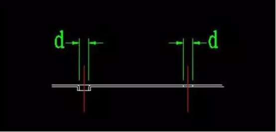
(2) Through holes on sheet metal surface or drawing holes. Uses screw tap to tap teeth, or M3, M4 mechanical teeth.
If lock with the screw with a diameter of 3mm, the hole diameter D is 2.6mm before tapping.
If lock with the screw with a diameter of 4mm, the hole diameter D is 3.6mm before tapping.
If the material thickness is 0.1~0.2mm, it is suggested to use a drawing hole rather than a through-hole as tapping M3 teeth with 1.2 mm material thickness can only get 2.5 teeth, which is easy for screwloose。
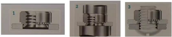
(3) Through holes on the plane of sheet metal parts and then rivet the self-clinching nut of finished products. The size of the renature D of the riveted fixing nut recommended by the manufacturer is better. While, when self-clinching nut, it should notice that stand-off/self Clinching-nut large manufacturer ——PEM (Penn Engineer & Manufacturing Crop) has specific riveting machines. However, it is riveted one by one, which wastes money and time. So, almost all factories use stamping machines to rivet. Nuts loose occurs when using traditional stamping machines due to the fast stamping speed. The process finished before the material filled out the nuts and Stand-off grooves. There are no issues with the appearance, but some nuts might fall off when assembling. Hence, a machine for riveting fixed nuts better has the function of adjusting speed.
6. EMI shrapnel material
Typically, common materials that we use to make the EMI shrapnel include: tinplate, corrugated copper, stainless steel, etc.
(1). The tin plating on the surface of the tinplate (Tin). Parts are likely to generate rust due to the sweat after being touched by hand. The cutting surface after the cutting process is likely to rust without no more treatments. The Tin is easy to stamp and form at a low cost, but has the poorest elasticity due to low carbon content, even after heat treatment.
(2). Titanium copper has the best conductivity but is the most expensive material fee. Due to the structural directionality, it is easy to crack. In production, it must be aware of the directionality of the material and can process elastic qualitative treatment to improve its elasticity if necessary.
(3). Stainless steel is best used due to its advantages of being stainless and strong, whereas the stamp molding is hard to achieve due to the wear loss and burrs. Good plasticity can only be obtained by the elastic qualitative treatment. Otherwise, it cannot recover if being over-compressed. If the cost-down does not receive elastic qualitative treatment, it is better to do a Stopper to prevent the shrapnel from being over compressed and cannot spring back.
(4). Typically, some metal materials protrude on two sides of the indentation angle after the ordinary sheet metal parts bend, causing the actual width is wider than the original size. How much the protrusion depends on the material thickness. The thicker the material, the bigger the protrusion. To avoid this, we can make a semi-circle on both sides of the bending line in advance. The diameter of the semi-circle is better than 1.5 times that material thickness. In the design of rim charge reverse folding. It is handled in the same way
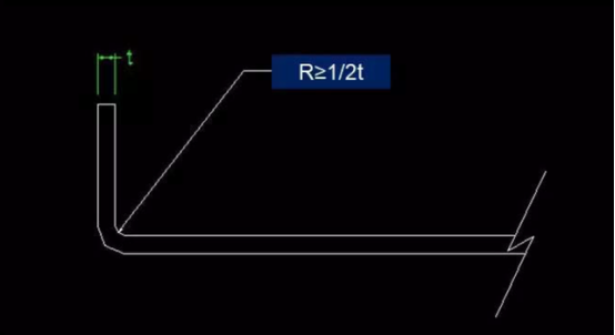
8. Bending radius
The internal R angle is better equal to 1/2 material thickness when the sheet metal parts bending.
If does not do R angle, after many times stamping, the right angle will disappear and naturally form the R angle.
After this, on the single and both sides of the R angle, the length might be a bit longer.
9. Bending height
The bending height is better over 3mm (t: 1.0~1.2mm), otherwise the structure might be unstable due to too few clamping size.
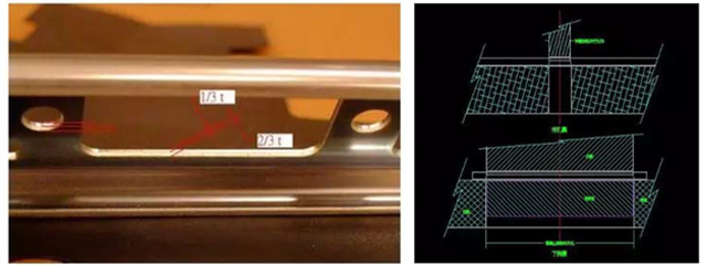
10. Punching and mold dimension
In blanking and punching of the sheet metal parts, the cutting fracture surface close to 1/3~2/5 of the die punching head is a complete and plane cutting surface. while close to cavity 3/5~2/3 is the draft section. Thus, in mold manufacturing or dimension inspection, the radius size is subject to the punch. The external size of the workpiece in blanking is subject to the internal size of the cavity.
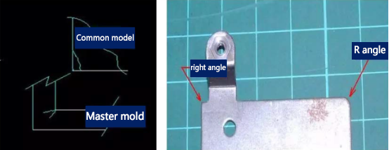
11. Angle R
On the angle of the sheet metal workpiece edges, if it is not specifically required to be a 90 degree, make sure to process it as an appropriate R angle because the right angle on the edges of the sheet metal workpiece will cause injury.
The tip of the right angle in the cavity is easy to form crazing due to the concentrated stress. The tip of the die is easy to be collapsed, so the mold must be repaired and delays the production. Even though the tip does not collapse, it will become an R angle due to a long-term abrasion and lead to unqualified products with burrs.
12. Bending and reinforcing rib
The sheet metal parts are more likely to deform under forces after bending. To avoid the situation getting worse, we can add a reinforcement rib at 45 degrees angle on the bend site to increase its strength without interfering with other components.
13. Rib reinforcement
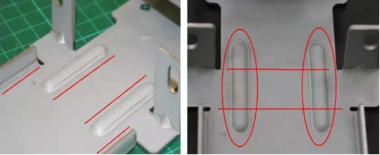
Typically, it is hard to keep straight when sheet metal parts are long and narrow. It is easy to deform under forces.
Thus, we can fold an edge into an “L” shape or fold both sides into a mouth shape to maintain its strength and straightness. However, the “L” and mouth shapes cannot connect from start to end due to some factors. How to fix it?
We can make an appropriate sized convex ribs to increase its strength.
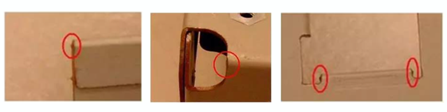
14. Marked on the chassis
Before the mold opening of the chassis, it is better to decide the location and size of the required labels in advance. We can label the chassis first for the convenience of applying the labels. Common two marking types:
(1). Mark “L” around the labels or on both left and right upper and downsides. In this way, the cost is low. However, the label protrudes from the surface of the chassis and is easy to be scratched.
(2). Increases the size by 0.3mm according to the shape and size of the label. We need to make a dent of a 0.2~0.3mm at the place to be labeled.
(3). No matter adopt which way, we can select one from four corners as one chamfer at 45 degrees to be used for foolproof. It avoids labeling at different times in different directions by each staff.

15. Wall in server chassis
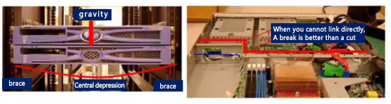
(1). The server chassis on the left and right sides are supported by sliding rails. Therefore, there will be no doubt of depression in the depth direction. However, transversely, the frame is 450mm wide. Besides, there is slide 10.mmX2 on the left and right. The casing width is around 430mm. It is quietly easy to sink on the central area of a 1.2mm wide and thick sheet metal piece. The chassis itself has front and back walls. If the chassis with a long length plus a middle wall in between can avoid the depression effectively. The design of the middle wall is best similar to the structure of C-type steel. Besides, the two side walls and the chassis bottom should be connected closely, so that the strength of the whole system is improved significantly, even though it cannot elongate towards the straight line. It would be better to have a gap.
(2). The middle walls increase the strength of the chassis, fixed fan, and air duct. If the contact between the internal of the upper cover is promised, it can effectively prevent the EMI and the noise from spreading from the mainboard. Hence, it is better to avoid placing the plastic parts on the middle walls since it separates the contact with the upper cover.
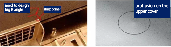
(3). Places that have gaps should avoid the acute angle, and do not forget to design the big R angle to prevent the generation of protrusion if the acute angle is against the upper cover due to high pressure on it.
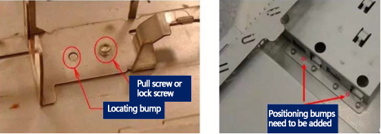
16. Bump location
(1). In the design of the chassis assemble, there is a two-part combination, three or four-part combination. Common fixed methods include locking screw, pull screw, hole drawing, riveting, or spot welding. In spot welding, there must be a locating point, locating pin, or the fixture to make sure a correct position. If there is already a screw hole or pull screw hole, no extra locating points are needed. However, the aperture of the screw holes is typically designed larger for the convenience of assembling. Therefore, there is also an error in the relative sites between the parts.
(2). It is suggested to locate with a locating bump with small gaps. In allowance analysis, it is accurate to process the benchmark operation by locating a bump with a small allowance.
17. Crack arrest grooves
The bending between the planes and bending surfaces is better with a crack arrest groove or to move the opening edge after the bend. Otherwise, the galling formed. While the width of the slot is better than 1.5 times that material thickness. Moreover, do not forget to mark the R angle when drawing. The mold cavities and cores with right angle or acute angle are easy to crack. The future shutdown and mold repair are both additional losses.
18. use complete 3D part without bending
This might be the basic issue that we can see. The metal plate is flat, so it has to operate with curving, forming, and laser cutting. Sometimes, it also needs welding. If design the sheet metal workpiece into a 3D one, you can send the CAD file to us. This file looks like folded, but needs to show the direction of the bending, which is essential. What is related is that the material thickness of the whole part must be the same as the raw material in the single metal plate. For example, if the established part uses 0.125 inches (3.175mm) thick aluminum, the thickness of your overall component should be 3.175mm thick, too.
19. Place the features too close to the bend line
If places the holes, lugs, or other special features are too close to the bend, the machining will be hard. How much is a suitable distance? Only by obeying the 4T principles to make all features at least four times the material thickness from the bending line. So, if you want to use 0.050 inches (1.27mm) copper to make your feature at least 0.200 inches (5.08mm) gap. If not, the features will deform in the bending machine.
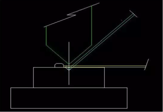
20. Design perfectly vertical sheet metal corners
(1). When the sheet metal is bent in the bending machine, the generated bend will not form a perfect 90 degrees. In contrast, this tool has a fillet tip, which can add a radius to the bending. If using the length of the area that you measured divides two, you can get the radius of the bending. The shape is defined by the tools of the place for bend manufacturing. If you have requirements about the size of the curve, you can specify them on the model to stress them.
(2). The common internal bend radius is 0.030 inches (0.762mm). One essential factor is that the radius of the external bend (radius formed on the bending machine mold side) equals the sum of the material thickness and internal bend radius.
21. Forget to contain the detailed hardware specifications in the CAD file
No one wants a long lead time. Remember that, through the detailed information in the top-level part information to let the manufacturers know which hardware you want. No matter the self-locking nuts such as cls-440-2, flat head studs like fhs-m5-15, and other hardware, this ensures that you get the accurate position you want.
22. Use the incorrect surface treatment (or not used when needed)
(1). Generally, surface treatment has two purposes: protect and beautify. Some people want both of them. However, they only focus on the appearance decoration but fail to anti-rust. On the one hand, the powder coating protects the part to some extent (unless the scratches affect the metal underneath). On the other hand, silk screen printing is used for adding text or images to parts. There is no protection at all.
(2). The chemical transition surface treatment aims to protect parts by altering the properties of the outermost layer. For example, if you want to use steel in a corrosive environment, you should consider galvanized or galvanized metal, which already got a protective zinc coating. However, be careful that we cannot weld the zinc-coated steel because it releases harmful toxins. By contrast, we can use steel to manufacture parts and then coated with zinc after welding.
(3). The chromate conversion makes the electrical connection of parts available, and it provides the bottom paint layer when painting. Anodizing adds metallic color to parts while protecting them.
23. Design unfeasible welding requirements
Have you ever tried to weld a line in a sealed box? Remember this if you want your weld requirement feasible. If the welding gun cannot access the weld seam, it is hard to perform the welding process. We strongly recommend finishing all the weld seams outside the parts when designing. The metal melts under high temperatures, so the material thickness must cope with the extreme heat. The lowest material thickness of welding is 0.040 inches (1.016mm) to ensure no molten metal generates from the weld seam. Lastly, always use the welding function or terminology to demonstrate your needs. Do not use a square frame to indicate welding.
No design skill can cover all sheet metal errors that we can see. You can check our sheet metal design guide to operate your project on the right track.
MORE BOLG
Insert mold in injection mold service
What are advantages and disadvantages of Zinc alloy and Aluminum alloy?
Inspection standards for injection molded partappearance
How to judge the quality of your plastic products?
Inspection standards for CNC machining
To ensure that your products are 100% qualified
Categories

Try GREFEE now,for free
We keep your uploaded files confidential and secure.