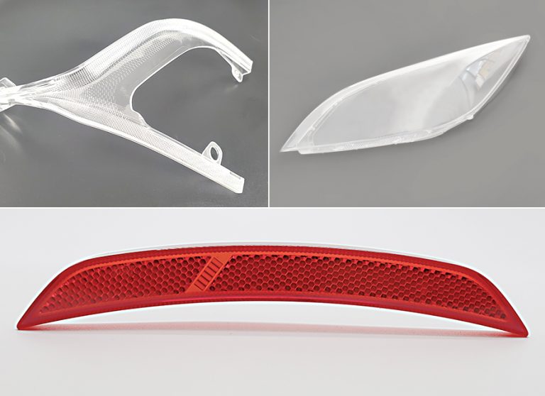
Threaded plastic products are seen everywhere in our daily life

Posted on : February 15, 2022 By GREFEE

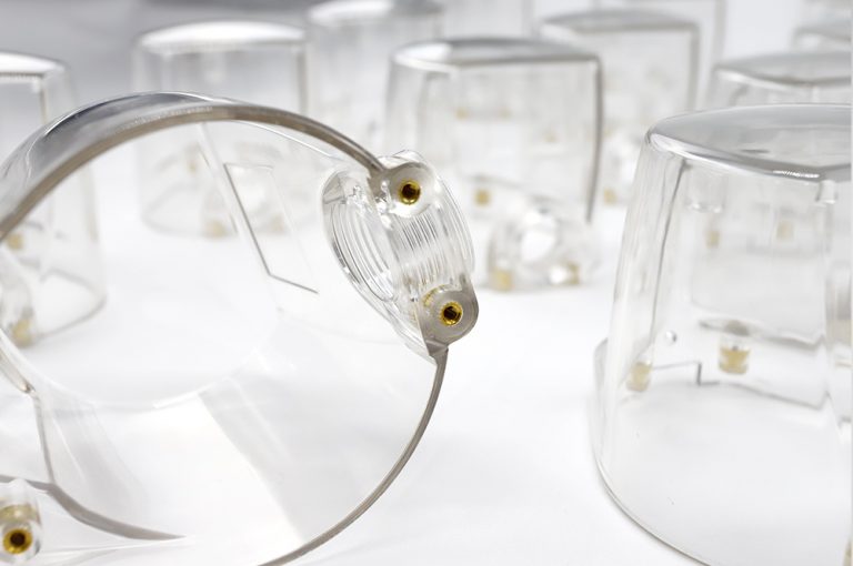
Threaded plastic products are seen everywhere in our daily life, such as bottle caps, connecting threads, etc.The thread injection molding products are everywhere in our daily life which can be found easily.The Injection molding thread is widely used in our life.
How to fabricate injection molding plastic parts containing ingenious threads elements?Not only the part design, but also the fabricating needs to be put in full consideration. Here at GREFEE Mold, we provide free DFM for threaded molding products.
Threaded Injection mold types
Internal thread of injection molding
The internal thread is the thread inside the products. We can use the forced demolding method if the internal thread products have low requirements.
On the other hand, we will need to use a kind of specific mold with special stripping mechanism if the internal thread products with high requirements.
ADifferent thread release methods lead to different production cycle time. Altogether, structure of external thread of injection molding is way simple than that of these molds.
You can also view the detailed cases of our threaded design molds.
The thread demolding methods
1. Forced demolding method
The choice for soft plastic products, like polyethylene and polypropylene should go for the semi-cricular coarse internal threads with shallow depth and remove the products out forcibly through the mold push plate.
Key points: due to the large demolding force, the pushing area should be as large as possible
This kind of forced demolding method is suitable for products with large quantity but low requirements for threads.
2.Manual demolding method
Manual removal at the external of injection mold.
After the injection mold opened, the mold core and thread ring will be pushed out of the mold altogether with the product before dealing with the threads through specific processing tools.
Features: the injection mold has simple structure, high manual operation efficiency but has a certain degree of operation requirements.Thus, multiple thread cores or rings need to be prepared for alternative use.
After opening the mold, Leave the products indie the mold and take out the thread core with a wrench. Low efficiency and high labor intensity.
This kind of method is suitable for projects with a small quantity needs.
3. Automatic demolding method
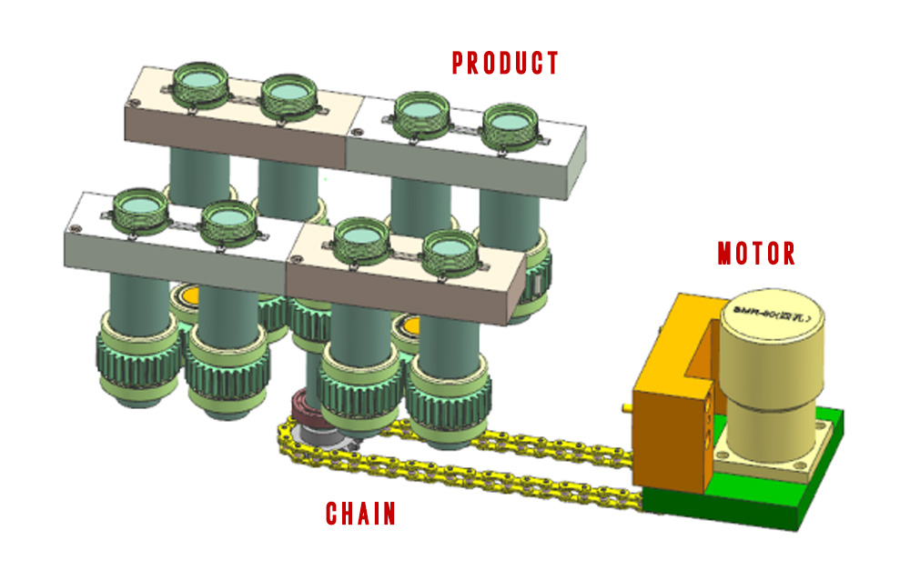
Automatic demolding method or fully automatic screw forming is an unique injection molding mechanism. Generally, it uses motor or oil cylinder to drive the threaded insert to rotate through the chain or rack to make it demold from the products.By using this method , you can obtain products with good appearance but the molding time is longer than that of manual molding, and the cost is relatively higher as well.
You could choose the way according to the production volume. When it goes to mass production, automatic demolding can help reduce the unit price. Your prime cost will be largely reduced even if it is only few cents saved per piece.
For more injection threaded parts support or more details, please contact GREEFEE team at info@grefeemold.com


Part Size:58 X 58 X 20mm / Material:PP / Cavity: 8 cavities
Motor + Chain thread removal structure
Mold thread types
Ⅰ. According to the move mode:
- The thread core rotates and separate products by the push plate.
- The thread core rotates and retreats at the same time, and the product separating naturally.
Ⅱ. According to the driving mode:
- Oil cylinder + gear rack.
- Motor / motor + chain.


Differences between oil cylinder & rack and motor / motor & Chain
Theoretically, the starting point of the thread should be accurate and it should be the mode of the oil cylinder & rack driving back mechanism, which can control the starting point of the teeth accurately.
If it is only rotation but no driving back, it possibly would be the motor & push plate demolding mode which is a method suits for the situation in which no requirements for the starting point of the teeth.
The main difference between the two methods is that, for the former, the more threads, the longer the rack will be. However, the number of threads of the latter has little effect on it.
The mold thickness of the former is often thicker than that of the latter. In addition, the chain transmission is relatively compact, with small tension and load on the shaft, high efficiency, suitable for mold transmission requirements, convenient to purchase and low cost, so the chain rotary is applied.
In terms of the selection of it, it depends on the customers’ requirements.


Common threaded products
Ⅰ. cavity internal thread: manually operated thread removal can be applied for a low volume product; while automatic thread removal structure is suitable for mass production.
Ⅱ.cavity and core internal thread:he external thread is generally made of slider structure. while the thread with high precision requirements, and no parting lines can only be applied into the automatic thread removal structure.
Ⅲ. Core internal thread:To detach the thread by manual operation is suitable for a small number of products; If the thread requirement, is not high, we could consider.When the material is soft and the teeth are very shallow, we can apply forced detaching (the thread is easy to deform). For large quantity, we can use automatic de-threading configuration to ensure the accuracy and mass production.
Ⅳ. Side internal thread: manual thread detach is often applied for low volume products; Automatic thread removal structure are more suitable for mass production.
Ⅴ. Side external thread: generally, it demolds directly through cavity and core molds parting, however threads with high precision requirements and no parting lines , can only use automatic thread removal structure.


The gate types of threaded products
There are kinds of mold gate types of threaded products: valve nozzle, pin point nozzle, pin gate, sub gate, edge gate, etc.
It’s not suggested to use sub gate and edge gate if the product has high requirements for thread accuracy and concentricity, for these two types of glue feeding are difficult to ensure the filling balance of each area of the product, which will result in inconsistent shrinkage rate of each area.
Valve nozzle: good flow performance, large degree of freedom in position, small gate. Suits large-volume production with benefits of saving materials, fast molding time, and high quality. Effectively utilizing gate materials without waste.The only disadvantage is slight gate marks.
Pin point nozzle: good flow performance, large degree of freedom in position, small gate, Suitable for mass production and can save materials, no waste of gate materials, short molding cycle and high quality. The disadvantage is that there is 0.1mm at the gate which is easy to cause . A groove should be made at the gate to cover the gate.
Pin gate: large freedom in located position, poor flow performance, long runner distance, small gate, suits for small-medium production, high volume of gate materials. In automatic production, it needs to clamp the gate. Long lead time. Disadvantage: 0.1mm ~0.2mm residue at the gate, easy to burr and need a sunk to cover the marks.
Sub gate: can be located at the cavity and core ribs, side walls and sub ejector pin. Flexibility in gate position, separating from the rubbers automatically, small gate marks. Disadvantage: easy to pull the rubber powder at the gate, dry marks at the gate, need to cut the film manually, great loss in press of the gate and cavity.
Side gate: when the melt plastic flows through the gate, it will be distributed more evenly in the transverse direction to reduce the stress of the plastic parts; Reduce the possibility of air entering the cavity and avoid defects such as silver wire and bubbles. The disadvantage is that the gate cannot be separated from the rubber products automatically.
Need tools to smooth the gate area as there is gate trace at the edge of the rubber part. Side gate can maintain a more balanced,injection and pressure maintaining as well as pressure maintaining feeding, which helps to improve the gas lines and flow marks in the gate area.
The design procedure
Ⅰ.Key data(see below pic)
- “D”——Outside diameter
- “P”——Thread pitch
- “L”——Thread length
- Thread specification / direction / number of heads
- Cavity numbers
Ⅱ.Determine the threads numbers of the thread core
U=L/P + Us
Turn numbers
The safety factor, generally 0.25 ~ 1 is to ensure the thread been completely screwed out.
3. Determine the gear module, number of teeth and transmission ratio. The module determines the tooth thickness of the gear, the number of teeth determines the outer diameter of the gear, and the transmission ratio determines the meshing speed of closing gear.
Before moving forward, it is necessary to talk about the parameters and meshing conditions of the gears.

Parameters and Meshing Conditions of gear teeth
The straight cylindrical gear is mostly adopted in the thread detaching mechanism, which is generally involute spur gears. Thus, below the involute spur gears are taken as the research object.
Ⅰ. Basic requirements for gear transmission
- The instantaneous transmission ratio should be constant
- Should have sufficient bearing capacity and long service life

Ⅱ. Basic law of spur gear teeth meshing
No matter where the two tooth profiles contact, the normal line must intersect with the connecting center line of the two tooth profiles at a contact point called ‘C point’, so as to ensure that the instantaneous transmission ratio of the gear remains constant. Connect all “C” points to form two circumscribed circles, which are called Indexing circles. The center distance of indexing circles is the center distance of gear circles. See the pics below for details

Ⅲ. Parameters of involute spur gear
The indexing circle diameter “d” indicates Perimeter of dividing circle
- “S”: tooth thickness
- “P”: Gear pitch
- “SK” gear slot width
- “EK” indicates the number of gear teeth
- “Z” indicates gear modulus
- “M” indicates gear pressure angle
- “ ɑ” Represents the gear ratio
- “I” indicates gear center distance
- “L” means

Ⅳ. The calculation formula is as follows:
① Pitch = tooth thickness + slot width, i.e. P = SK + EK
② The origin of modulus is because s = Z , x , P π x , d = P π x , Z
π is an irrational number. To make the calculation more convenient, P / π is specified as a constant, i.e. modulus, expressed in M, the formula is as follows:
d = m x z
Notes: the pitch diameter equals to the modulus times the number of teeth. According Chinese standard, there are two series of modules, and the first series is preferred.
Module 1 Series:
1、1.25、1.5、2、2.5、3、4、5、6、8、10…
Module 2 Series: 1.75, 2.25, 2.75, 3.25, 3.5, 4.5, 5.5, 7
③, Pressure angle
According Chinese standard, the pressure angle at the dividing circle is the standard pressure angle, which is 20 °.
④ Transmission ratio
When the modulus is constant, the transmission ratio is equal to the gear ratio, i.e. I = Z1 / Z ^ 2
⑤ Center distance
When the number of teeth is determined, the center distance I = (z1 + Z2) / 2 * m 5
Ⅴ. Gear Meshing Conditions
Modulus and pressure angle
The same gears can mesh correctly.
1. Number of teeth
When the transmission center distance is constant, the more teeth there are, the more stable the transmission and the lower the noise will be.
However, with more number of teeth, the modulus and tooth thickness will be lesser, resulting in the reduction of its bending strength,
Thus, we should take as more teeth and smaller modulus as possible when under the condition of meeting the bending strength of the gear.
To avoid interference, the number of teeth is generally Z ≥ 17, and the number of teeth of the threaded core is as few as possible, but at least 14 teeth, and it is better to take an even number.
2. Modulus
The industrial module gear is generally m ≥ 2.
The Imperial gear uses diameter pitch system, the ratio of the number of teeth Z to the diameter d of the indexing circle is identified as the diameter pitch by “P”
”That is, P = Z / D, the conversion formula between 1 / in diameter pitch and modulus is m = 25.4/p, mm
3. Transmission ratio
The prime number of transmission ratio is selected under the condition of high-speed, heavy load or open transmission, in order to avoid failure concentrated on the teeth. The transmission ratio is also related to which driving mode is selected. For example, when the rack & taper tooth or rifle line nut are used for driving, the transmission must be larger because the transmission is limited by the stroke, which is generally 1 ≤ I ≤.
4. When oil cylinder or motor is selected, due to unlimited transmission, it can not only compact the structure and save space, but also reduce the instantaneous starting force of the motor, moreover to slow down the rotation speed of the threaded core, generally 0.25 ≤ I ≤ 1.
Ⅵ.The design and calculation of thread removal mechanism
For general rotating mechanism, the rotation numbers of thread core depend on the threads numbers of the products.
However, the thread removal of the mold on the angle injection molds is driven by the opening and closing of the screw rod in the mold. Therefore, the difference of pitch should be considered.
The screw rod consists of forward and reverse threads, so every time the screw rod rotates one circle, the thread core rotates the same, and the cavity mold moves two pitches.
Cavity mold opening stroke L = 2NT
N: Number of threads in the product. T: Screw pitch.
L: The mold opening stroke, must be within the opening stroke of the injection mold, otherwise the speed change mechanism must be designed.
If the speed change mechanism is designed and the ratio of the number of teeth of the driven gear to the driving gear is I, the thread will move axially each pitch T every time when it is rotated, the screw rod needs to rotate I times, and the cavity mold will move 2It. Usually, T> t, so parting is also required in the core mold to make the cavity plate move a certain distance along the mold opening direction.
Otherwise, it will cause the cavity loose the role of stop rotation. Because the core withdrawal speed is less than the moving speed of the core mold, when the thread of the product has not been completely screwed out, the product has withdrawn from the non-rotating cavity, so that the product can’t demold smoothly.
Therefore, it is necessary to correctly design the parting distance L1 of the cavity mold. The core has been rotated out but the product has not withdrawn from the cavity if L1 is too long. However, if L1 is too short, the product will demold from the cavity completely while there are still several threads are not screwed out.
When there are still n threads which have not been screwed out, the fixed mold stops parting, and the product is still in the cavity. So: n = H / (2it-t), where h is the height of the product. L1 = (N-N) (2it-t) = 2int-h-h, where h is the height of the threaded part of the product. Total mold opening distance L = L1 + H + H = 2int + 5 ~ 10mm
The relative movement distance between the square shaft and the screw rod is half of the mold opening stroke, so the length of the square shaft L1 = L / 2 + a. A is the length of the fitting part (generally 25mm).
Ⅶ. Cooling of thread mold
As the thread core rotates and is hard to cool down soon, so it needs a cooling core in the centre of the thread core of the mold. With the cooling water flowing into the thread core through the steel pipe, a circulating flow is formed. There are eight direct waterways in front mold cavity and the external water pipes form a circulation for a better cooling effect.
In addition, beryllium copper is a good cooling material that can be used in the thread core to reduce the forming cycle, but the manufacturing cost is high, which is suitable for large quantities. Beryllium copper is also widely used in medical products.
Nowadays, with the breakthrough and promotion of metal printing technology, many water transportation structure system can be directly printed out with balanced shape
, which solves the difficulties of machining problem, so as to greatly realize the high-efficiency in cooling.


Ⅷ、 Common problems of thread mold
1. Product thread damage: check whether there’s undercut or burrs in the thread mold, which is easy to cause damage during product rotation.
2. The product rotates with the thread: if the rotation stop position is not enough, the reverse angle can be reduced; Add polishing on the thread mold; Check whether there are undercuts, etc.
3. Inconsistent starting position of thread products: increase the positioning of reset structure after thread rotation to ensure that the end position of each reset is consistent.
4. The product will not fall off automatically: add polishing on the mold, and increase the ejection structure if there’s space
5. Unbalanced material flow of the product: check whether the gate size of each cavities is consistent; Check whether the insert temperature of each cavities is consistent; Check whether the wall thickness of cavities is consistent. If there is little difference, we can increase the gate appropriately for those cavities with slow material flow to adjust the melt material flow balance
Ⅸ. Thread inspection method
There are generally two ways for thread measurement: single measurement and comprehensive measurement. Single measurement is often used to inspect the pitch diameter, pitch and tooth semi-angle of thread.
The conventional pitch diameter measurement methods of cylindrical thread include:
① Measure with a thread micrometer.
② Put three cylinders with the same diameter – three needles, into the threaded alveolar, and then measure them with micrometer, get M with comparator or length measuring instrument (see length measuring machine) .Then, after calculation, the pitch diameter D1 of the measured thread can be obtained.
- Image measurement by tool microscope.
- It was measured by axial cutting method on the tool microscope. Comprehensive measurement is to check the actual pitch diameter error and converted pitch diameter error of thread to control the screwing quality of thread. The converted pitch diameter error is the error of converting the pitch and tooth half angle into the pitch diameter direction.
At present, the relatively advanced measurement method is the thread indicator gauge measurement , which divides the thread measurement into single pitch diameter measurement and active pitch diameter measurement. This method can measure the pitch diameter, roundness, pitch, profile angle and taper of the thread, and the runout of the end face or thread can be measured by adding a probe.
The single pitch diameter is the single tooth pitch diameter, and the acting pitch diameter is the full tooth pitch diameter. If the measured values of the single pitch diameter and the acting pitch diameter are the same, it indicates that all parameters of the thread are qualified.

Common problem
1. In the thread production,What cause the gear shifting stutters?
A: If there is no problem with the mold design and inspection, then in most cases, it should be the reason of machining accuracy. As the concentricity of the gear should be fixed, and the distance accuracy of the concentric distance in the middle of the gear should also be fixed when it is assembled. The matching between the gear profile is critical, so it is necessary to make sure a precise machining process to prevent such problem in the later stage.
2. When the thread rotates backward, the products will rotate with the threaded insert and will not fall. What is the problem?
A:In this case, it indicates that the rotation stop feature exists, but the force of the rotation stop feature may not be enough. It is necessary to make a smaller angle with the rotation direction to form a reverse force. In addition, check whether the products that will not fall are caused by the reverse buckle of the screw teeth or the problem of the rotation stop processing data.
3. How to process to ensure the concentricity of thread rod?
A: CNC lathing can ensure the concentricity after one-time processing. As we know, if there are retreating screw teeth at the rear end of the screw rod, many of them will be made into inserts to simplify the processing, but this will cause the problem of non-concentricity. Therefore, the inserts and the screw rod should be positioned, assembled and matched together to turn the shape together, so as to achieve the concentricity, In this way, the screw tooth rotation can run smoothly.
4. How to determine whether the threaded products fall off automatically or push the plate to push the products out?
A: It is easy to deal with. To check if the product has stop characteristics. If so, the backward product can fall off automatically. If not, we could only choose the push plate to push out the products.
5. How to calculate the strength of the rack drives gear and the Rifle line pulls the gear? How can we control that the lever or rack will not be damaged?
A: the Rifle bar has corresponding stress range parameters, which can be directly selected. For the strength calculation referred, we need to calculate the demolding force required by the product first. There is a formula that can be calculated, which is very troublesome. It is rarely used in actual work, and it is mostly taken by experience.
My advice is to be as large as possible, because the calculated datas are not necessarily accurate, This is also related to the tightness of die matching, machining accuracy, wear in the production process and many other factors. Therefore, we can not lump together.
6. How to determine the sealing part of thread core, straight or taper?
A: There’s no doubt that taper is better. This is as same as the straight movable insert. It is a fake work. It’s hard to match the mold if the sealing part has not been done well.
7. Some threads are removed by force . How to determine this?
A: It’s only suitable for the threads with shallow depth and has low requirements on the thread section distance and accuracy.
8. How large is the design of the shaft of the automatic thread removal gear die, that is, the thread core? For example, for products with a diameter of 40 and products with a diameter of 10, how large is the shaft diameter? Does the strength need to be calculated?
A: the diameter of the shaft is generally the inner diameter of the bearing closest to the product diameter. For example, when the product diameter is 40 and the sealing inclination is made, the rod must be greater than 40. According to the bearing standard, the nearest bearing model with an inner diameter greater than 40 is 45. Then, the diameter of 45 is more appropriate.

GREFEE Mold has a professional technical team, equipped with imported injection molding machines and advanced imported processing equipment.
We have rich experience in the production of thread molds, we provide customers with the most reasonable analysis reports of products, including parting line position, gate position, ejection position, thickness analysis,demolding angle analysis, deformation range analysis and molding cycle.

What’s more, we can provide the most professional solutions for customers in steel material selection to successfully go on the market.
MORE BOLG
Categories
Latest blog

Try GREFEE now,for free
We keep your uploaded files confidential and secure.
