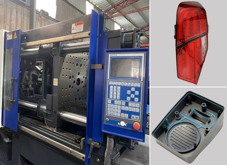
Insert mold in injection mold service
Posted on : Dec 18, 2021 By GREFEE
Insert mold generally is a kind of mould that make nuts, metal parts or hard plastic parts fixed inside cavities for injection molding.
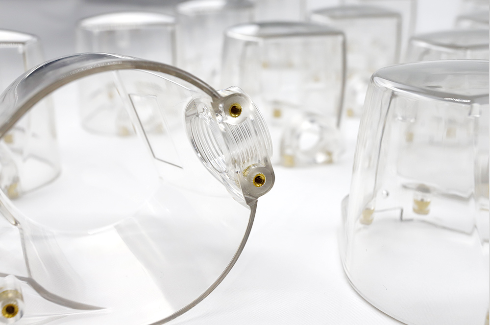
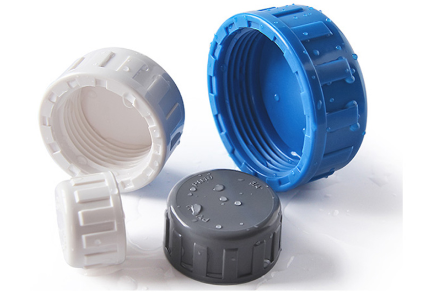
Insert nuts injection molding: nuts material can be stainless steel, copper, bronze and steel, generally copper nuts are commonly used. Copper is easy to knurl, which helps nuts and plastics splice better. The tolerance of nut inner bores should be controlled within 0.02mm, otherwise easily cause flash if the tolerance beyond 0.02mm. In mould fitting, need to assemble nuts into insert pins for testing. If it’s tight fitting between nuts and pins, it would be hard to ejector the part and cause eject marks or sticking problems. If it’s loose fitting, it would cause flash.
Insert screw-nut injection molding
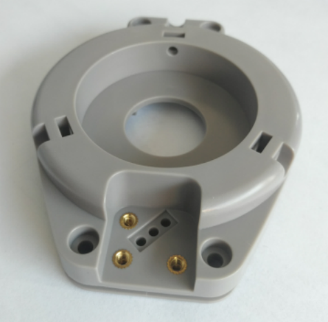
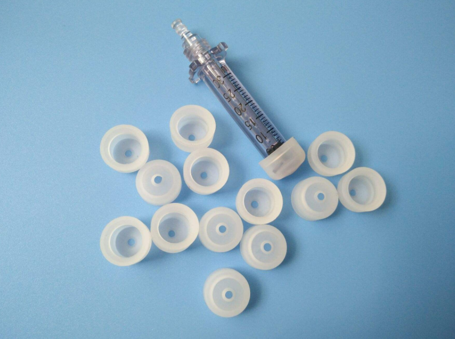
Insert metal injection molding
Insert metal parts injection molding:
Metal parts can be stainless steel, aluminum, copper, steel …etc. The tolerance of metal parts should be controlled within 0.02mm, otherwise it’s hard to seal material and easy to have flash. The acreage of metal parts cannot be designed too large.
If the filling acreage for metal parts is too large, it would be very difficult to achieve fully injection as great temperature difference between metal parts. Positions of metal parts are usually designed in cavity as cavity doesn’t move, which helps avoid flash result from metal parts loosing in moving(in severe case, may damage mould). In particular cases, positions of metal parts can only designed in core or side surface of the product.
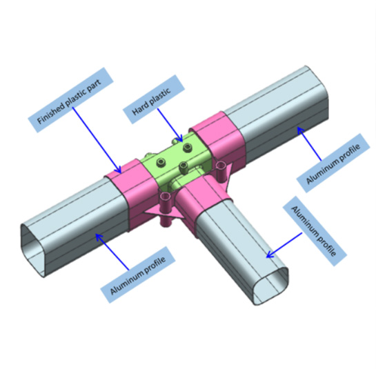
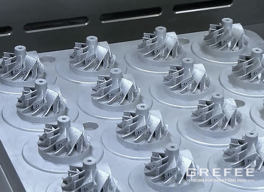
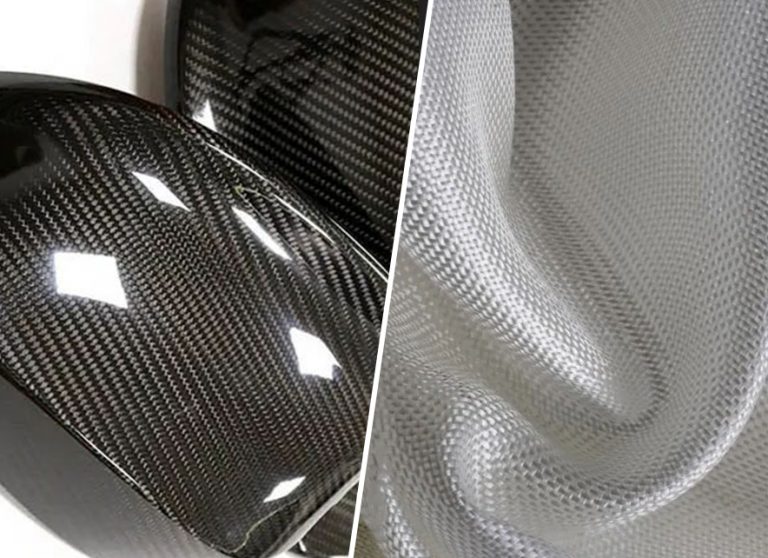
Insert hard plastic injection molding:
Usually choose hard plastics with high melting point, such as PEEK, PA66+30GF, PP+30GF, PA12+30GF, PPS….etc. Tolerance for these hard plastics should be accurate. Defects like shrinkage, dent, and deformation cannot exist in sealing area. In mould fitting, the hard plastic should be put inside mould for testing, and left 0.05-0.1mm pre-pressing around sealing area to achieve better sealing.
The hard plastic part shouldn’t be designed too large acreage, which will cause temperature difference and make it difficult to fill material in injection. Usually make the hard plastic part fixed in the side of cavity, because cavity doesn’t move , to avoid flash or even damaging mould in mould moving. In particular cases, positions of metal parts can only be designed in core or side surface of the product.

Try GREFEE now,for free
We keep your uploaded files confidential and secure.
PEEK, PA66+30GF, PP+GF, PA12+30GF, PPS material melting temperature parameters
| No. | Materials | Melting temperature |
| 1 | PEEK | 280~330 |
| 2 | PA66+30GF | 270~320 |
| 3 | PP+30GF | 230~275 |
| 4 | PA12+30GF | 210~250 |
| 5 | PPS | 300~340 |
Design key points
- Design shrinkage for products with nuts inserts, while no need design shrinkage for products with metal parts and hard plastic inserts. For areas which need strict tolerance, modify the products’ size tolerance to median.
- Usually adopt mould base with standard pin-point gate in mould designing, and in secondary injection, put the inserting parts in cavity as much as possible. On the condition of making the inserts fixed in cavity, consider how to make part left in core after injection molding, in this way, part can be ejected. Usually add elastic blocks in cavity and elastic glue to make part stay in core. The distance between elastic blocks and glue cannot be too large, otherwise the elastic force will cause hard plastic or metal parts deformation. The distance usually is designed within 2mm, and appropriately increase the quantity of elastic blocks and elastic glue when the metal or hard plastic inserts have relatively large acreage.
- Thickness of material is best within 1.3-1.8mm(around 1.5mm is the best), if not, need to check through the product drawings and suggest customer modify it. If material thickness is thinner than 1.3mm, it’s hard for material filling, while material thickness is thicker than 1.8mm, shrinkage is easy to happen in production.
- Gating is very important in mould. The balance of material filling for gate point should be fully considered.When material runs to the area where metal or hard plastic parts are fixed, the speed of material filling and pressure will lower down because the inserts resistance and temperature difference.
- For mould ejector system, The balance of ejecting must be considered or the deformation will happen after ejecting. For parts cannot be ejected in balance, need to consider collapsing to improve the balance problem in structure design.
- To assure the qualification of parts’ appearance after being ejected in injection molding, the ejector device must be hard plastic lump inserted with ABS or PMMA. If over mold has slide sealing, design slides in cavity as much as possible, because slides in cavity facilitate mould fitting.
- To assure the strength of sealing S.A.(seam allowance), for product made from twice injection molding, the width of sealing S.A. should be at least 0.8mm. For the secondary injection material is hard plastic, the width of sealing S.A. should be at least 1.0mm, otherwise, need suggest customer to modify the product.
- In mould design, we should take the injection molding machines into consideration for production to see which type of machine it adopts, vertical or horizontal. It is suggested that do not design too many cavities, especially for mould with cold runners as too many cavities make runner longer, wasting material and is also harmful to achieve high-efficiency injection. To match injection molding machine, we must consider whether it’s compact and reasonable for the product arrangements.The products must can be fixed to assure the products are in same situation each time when they are put in mould. Another way is the design reaction system to alert if the part is not in right place before mould closing, which helps stop mould closing. In this way, parts are in the same situation in mould, which raises the qualified rates and production efficiency in injection molding.
- A steel support must be designed as the mould injection area bears great pressure in injecting (should be 5-10 mm larger than that of part in shape and size). Mustn’t left gap between parts around Over-molding area, otherwise the part will be out of shape after the secondary injection. For parts without S.A.(seam allowance)will need pay much more attention to this aspect.
- Air trip is easily Air trip happens easily in injection molding, so must fully consider venting in mould designing. In all blind angles and positions for long-distance water line, must design venting holes on hard plastic part as it’s much more harder to fill material in blind angles.
- To assure the injected material and qualified thrust are fully filled, one way is to design an undercuts at the corners of part to enhance adhesive result and then to make parts adhere more tightly.
- In sealing area and parting line area, we shouldn’t demould from cavity and core, because clamping lines in mould and demoulding draft will cause flash in mould fitting. Try to demould by LISS-OFF.
Try GREFEE now,for free
GREFEE has many years of project experience and can quickly help your project
Gate point types of insert mould
Gate point for insert mould can be designed to direct hot sprue valve gate, hot sprue pin gate, pin-point gate, sub gate, edge gate…etc.
Hot sprue valve gate: good liquidity, position selecting flexible, small gate point. Suits for massive production and for products with thick wall thickness. Can help save material, no material waste for gate, short lead time, and high quality. The only defect is the slight gating trace.
Hot sprue pin gate: good liquidity, position selecting flexible, small gate point. Suits for massive production and for products with thick wall thickness. Can help save material, no material waste for gate, short lead time, and high quality. But there’re defects, such as 0.1mm material left around gate point, and easy to burr. Need make grooves to cover the left material around gate point.
Pin-point gate: position selecting flexible, weak liquidity, long runner distance, small gate point. Suits for small batch production. More waste material around gate point. Need mechanical arms to clamp gate point in production. Long lead time. Defect is 0.1-0.2mm material left around gate point, need make grooves to cover the left material around gate point.
Sub gate: can be designed on ribs in cavity, core, side walls, and ejector pins. Can select gate point flexibly, pouring gate separates from part automatically, slight gating trace. Defects: easy to pull material out around gate point, easy to cause drying marks in gating position, need wipe out material by hand, much press loss from gate point from cavities.
Edge gate: molten plastic flows through gate, are assigned lateral evenly, decrease stress; decrease the possibility of air entering cavity, avoid causing streaks and bubbles. Defects: pouring gate cannot separate from part automatically, left sprue marks on part’s edges, need tools to process pouring gate flat. Edge gate can help proportion injection and pressure holding, and also is good for pressure holding and feeding, in this way, it’s better for improving air lines, flow marks…etc,
Parameter values for popular materials used in venting system
| Plastic | Exhaust tank depth(mm) | Plastic | Exhaust tank depth(mm) |
| PE | 0.01 | PMMA | 0.02-0.03 |
| PP | 0.01-0.015 | PC | 0.012-0.025 |
| PS | 0.02-0.03 | POM | 0.01-0.03 |
| ABS | 0.015-0.02 | PBT+30GF | 0.03 |
| ABS+PC | 0.02-0.03 | PA6 | 0.01 |
Processing and fitting for insert mould
1.Before processing, work out the processing technology of mould. Choose high-precision processing machines, high-speed machine, slow-feeding NC wire cut machine, mirror EDM(electric discharge machining) machine etc.
2.Design 0.05-0.1mm left in location of pre-pressing.
3.Note precision requirements in mould base processing, inspect tolerance after get the mould base and not use it if the tolerance is unqualified.
4.Put nuts, metal parts and hard plastic parts inside mould for mould fitting. If find problems in mould fitting, check through nuts, metal parts, hard plastic parts and moulds to see which one is wrong. Process part according to drawing as far as possible, which helps trace data in the future.
5.Cannot use grinder for mould fitting. Turn to machines for correcting where mould fitting is not good.
6.Do action testing before trial, avoid miss assembling and mistaken assembling. Mistaken assembling will cause damage of mould base.
Mould testing for insert mould
1.In a mold testing, one needs to know clearly about the sequences of opening, closing and ejecting a mold. Understand the structural features and properties of metal parts and hard plastic parts.
2.Know clearly about the samples quantity that customer need, prepare enough nuts, metal parts and hard plastics, because it needs many samples in mould testing.
3.Note whether can test mould without inserts of nuts, metal parts or hard plastics. If insert nuts, metal parts and hard plastics are not assembled in mould, part may have defects such as sticking to mould or short shot.
4.In many cases, need to adjust the waterline plate on mold, but sometimes it cannot adjust water line plate in some insert mold based on their structure, or even worse, mold is heavily stuck and need modifying, or mold being damaged in the opening.
5.Problems may happen in mold testing, such as short shots, air trips, flashes, or sticking to the mold. If problems can be verified on an injection molding machine, it’s better to solve it.
Common problems in parts made by insert mould
- not enough inset size.
- not enough processing in insert locations.
- not fully fixed of inserts in mould.
- too large acreage of inserts.
- not enough insert positions.
- inserts in core and are swaying in mould moving.
- too large pre-press in the secondary injection.
- mould base without gaps or not enough gaps.
- insert loose or deformation causing part crushed.
- not enough pre-press in mould base.
- metal parts surface have dents, defective dimensions, or short shot in hard plastic products.
- non-performing dimensions of mould base causing not enough thickness.
- may be too high temperature of material or mould.
- mould without venting system or venting not enough.
- incorrect gate point.
- unhealthy conditions of injection molding, such as low temperature of material and mould, or low speed of injecting and press.
- Temperature: injection molding technology requires plastics in molten situation for processing, so it has strict requirements for the surrounding environment. If the temperature is too high, the material is too soft to lose toughness thereby more easier to cause crack. High temperature cause degradation inside material then break the plastic molecule structure, which causes internal crack.
- Material filling speed, generally we require the fastest speed of material filling, because crack and deformation are easy to happen with low speed of material filling.
- Press, in injection molding, too large press, too quick speed, too much material, and too long time injection and pressure maintaining will cause too much internal press then cause crack and deformation.
- Mould use is also one of the reasons for crack in injection molding. Should use metal inserts as less as possible in mould, to avoid increasing internal press by different shrinkage between part and insert. Need balance ejecting, such as design enough ejectors, sectional surface, demoulding draft, and smooth cavity surface, which helps avoid cracks caused by stress concentration and ejection residual by external stress.
MORE BOLG
Categories
Latest blog
Try GREFEE now,for free
We keep your uploaded files confidential and secure.