How to Fix the Shrinkage Deformation of Injection Molded Parts

Posted on : July 30 , 2022 By GREFEE
It is inevitable to meet defects like warping when designing injection molded parts.
So how to fix the warping?
First, we must understand what causes the injection molding parts warping?
After knowing the fundamental of the basics, we can start from four aspects, which are plastic materials, plastic parts design, mold structure and molding process.
Certainly, the prevention is more important than the fixation in dealing with warping. We must optimize according to the four aspects before the part warping rather than fix it after it has already happened, which is more complicated.
Warping is common.
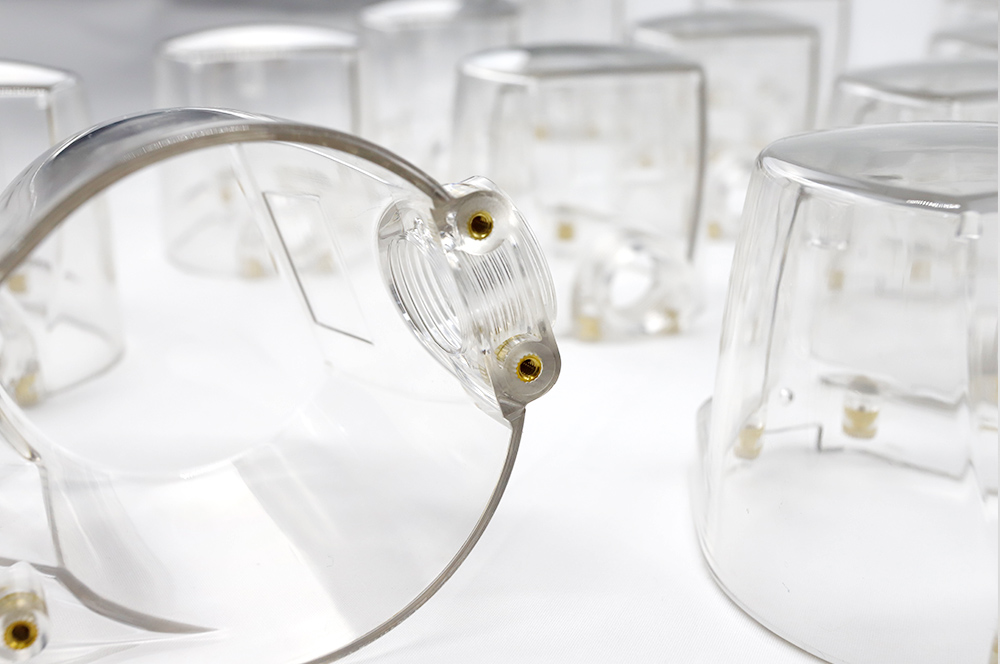
Warpage in plastic rubber part: it is one of the most common defects to plastic rubber part and either to any product, which is also one of the hardest defects to fix at the same time.
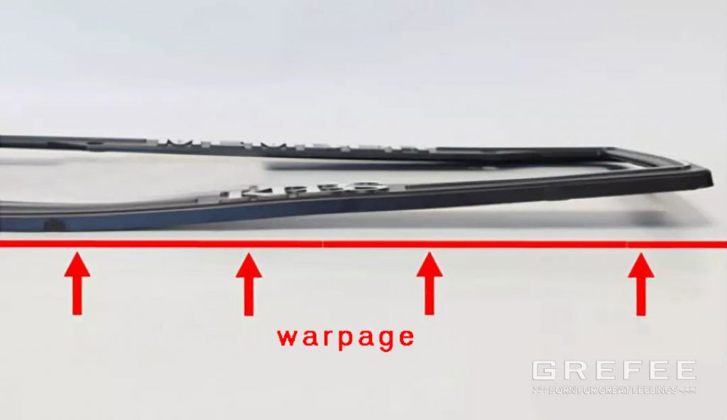
▲Warpage in plastic rubber parts
Outcome of warpage
Typically, warpage affects product appearance because it may cause non uniform appearance clearance and gap. Consumers may lose interest because the poor appearance lowers the product grade. Server warpage affect the assembly, or even the function, performance, and reliability.
Fundamental reason of warping — uneven shrinkage
1. Why uneven shrinkage mainly contributes to the warping? The cause for warping of the plastic rubber part is the uneven shrinkage of the plastic.
If the plastic rubber part shrinks on each direction evenly during the injection molding process, the size of the part will become smaller but maintains the correct shape rather than warping. However, inconsistent shrinkage on any direction will lead to the internal stress. When the internal stress exceeds the strength of the part, the plastic rubber part will warp after the ejection.
2. What is shrinkage? before getting to know the srinkage, we need to understand the rubber material shrinkage. Thus, we starts from the molecular structure of plastic materials to see various changes of the rubber material during the melting and cooling processes.
For most plastic rubber materials, the properties of the melting and cooling processes rely on the category of material and whether there is any filler or fiberglass.
(1). Amorphous plastics.
Amorphous plastics refers to plastics in which the molecular are displayed in a disordered status without crystal structure. Common amorphous plastics include ABS, PC, PMMA, PPO, etc. the ABS, PC, PMMA, PPO, etc. The molecular arrangement of amorphous plastics is disordered no matter it is in the molten state or solid state.
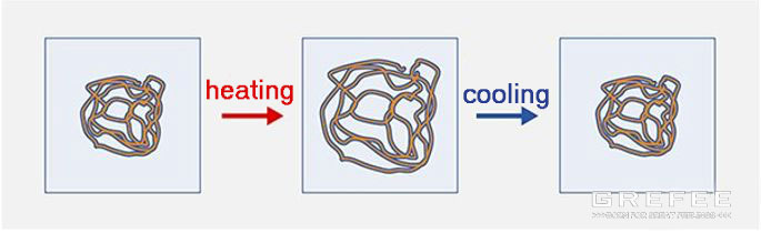
When the amorphous plastics melting, the energy between the molecular becomes weaken, which makes the molecular move between each other. In addition, the shear force (similar to friction) in the filling stage makes the molecules spread, and the molecular orientation is consistent with the flow direction of the solution flow.
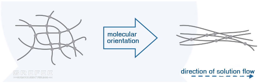
When the solution stops flowing and molecular relaxes, it returns to the disordered state. The force between molecular forces them to get close to each other until the temperature is low enough to solidify them. These forces lead to uniform shrinkage. However, the relaxation effect will cause more shrinkage in the direction of solution flow.
(2). Semi crystalline plastics.
The semi crystalline plastics refer to plastics with regular crystal structure in which some molecules are displayed with each other in the solid state. This type of crystal structure is dense and more compact. Common semi crystalline plastics include PBT, PA, POM, PPS, peek, etc.
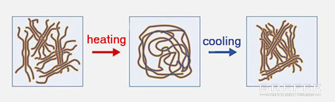
During the melting of the semi plastics, the grains become loosen. the orientation of the molecular is consistent with the solution flow direction, and is almost same with the amorphous plastic. However, during the cooling process, this part do not loose. Conversely, they still remain the same direction as the solution flow direction and start to crystalized, which increases the shrinkage rate significantly. The relaxation effect makes the shrinkage rate of the solution flow direction is higher than that of the vertical direction. The shrinkage rate of the semi plastic is high. At the same time, the semi plastic has different shrinkage rate in parallel and vertical directions, which makes the problem more complicated. The situation becomes worse because of the changes in the injection molding conditions will change the crystallinity. If the plastic is cooled slowly, the crystallinity and shrinkage rate will be improved.
(3). Glass fiber reinforced plastic
The glass fiber is a type of material added into the plastic to enhance the mechanical strength and other properties. It has an effect of eliminating the shrinkage due to the orientation of the molecular. When temperature changes, the glass fiber do not inflate or shrink. Thus, in the solution flow direction, the glass fiber will reduce the shrinkage rate of the plastic.
What contributes to the uneven shrinkage? There are manly five aspects.
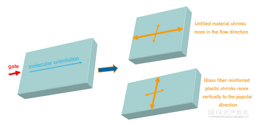
influence of the molecular orientation when filling
At the beginning of the filling, the shear pressure makes the plastic molecular orientation. When the filling stops, the plastic material is still under a high temperature but the shear force disappears and the orientation is relaxed (orientation only maintains when the shearing and solidification happen simultaneously). For amorphous plastic, when the orientation is relaxed, the shrinkage parallel to the flow direction of the solution is larger. For glass fiber reinforced plastics, the shrinkage is larger in the direction perpendicular to the melt flow, since the molecular orientation of the crystalline part is consistent with the melt flow direction. The crystallization occurs in the direction perpendicular to the melt flow direction.
Mold structure restriction
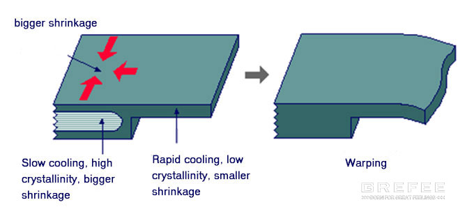
When the plastic rubber part is in the mold, the part cannot shrink in the plane direction due to the restriction of the mold structure, but can shrink in the thickness direction. This has two effects. The first one is the shrinkage in the thickness direction is more. The second one is the residual internal stress concentrates on the plane direction. After the ejection, the part will warp due to the stress release as the continual cooling without the restriction of the mold structure. The higher the mold temperature, the slower the cooling speed, the higher the stress release. The mold structure is affected by the plastic rubber material. Plastic material with slow stress release have larger linear shrinkage. Plastic materials with faster stress release have smaller linear shrinkage.
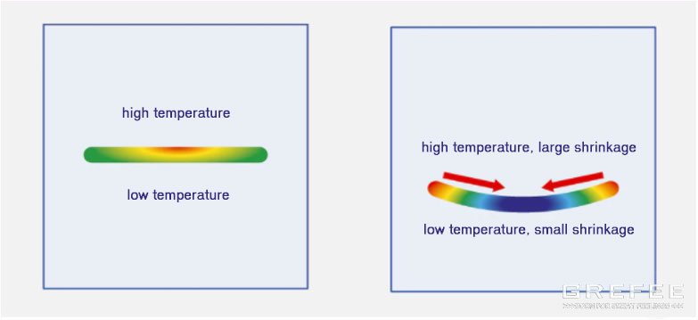
Temperature difference in the wall thickness direction. When the mold temperature of two sides in the plastic parts thickness, the shrinkage is uneven. Generally, the side with higher mold temperature has larger shrinkage, whereas the side with lower mold temperature has smaller shrinkage. Thus, a moment of deflection generated and causes the warpage.
Uneven wall thickness
Uneven wall thickness will lead to longer cooling time, since the thick area takes longer period of time to cool sufficiently and leads to larger shrinkage.
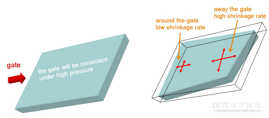
uneven pressure holding
The inside areas bears a different level of holding pressure. The pressure is larger around the gate. Under the pressure of the area far away from the gate, it will cool at different speeds, resulting in uneven shrinkage.
(4). Four manifestations of uneven contraction, generally speaking, uneven contraction is mainly manifested in four aspects:
Uneven shrinkage of different parts of the product
The shrinkage of the area near the gate and the last filled area on the plastic part is uneven. The shrinkage of the area near the gate is small, and the shrinkage of the last filled area is large.
Uneven shrinkage along the product thickness
From the perspective of the thickness profile of a plastic part, the shrinkage of the upper and lower areas of the profile is uneven. This inconsistent shrinkage will lead to warpage of plastic parts, for one side shrinks more and the other side shrinks less.
Uneven shrinkage in parallel and vertical directions of molecular orientation
Due to the molecular orientation or fiber direction, there is uneven shrinkage in the direction that is parallel to and perpendicular to the plastic melt flow. Based on above, unfilled plastics shrink more in the direction of melt flow, while glass fiber reinforced plastics shrink more in the vertical direction.
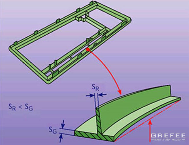
Uneven shrinkage in the plane and thickness direction
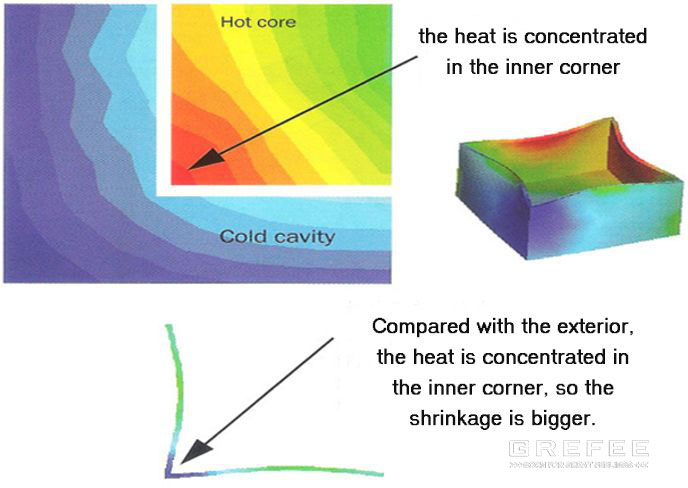
The shrinkage in the thickness direction if often larger than that of plane direction, which is due to the mold structure restriction in the plane direction. This does not exist in the thickness direction. The uneven shrinkage will lead to warpage, especially in the corner of the plastic part. In these area, the wall thickness of the part is often larger than the basic wall thickness of the part.
Structural thinking in preventing and fixing warpage
1 .Prevention outweighs the fixation.
The warpage must be prevented earlier in the products design stage rather than wait until the mold processing completed, or warpage occurred in mold testing. Once the warpage is happened, it is hard to fix it and there is less measurements to solve it.
Special or extreme injection molding processing conditions (special mold temperature, high mold temperature difference, longer injection molding cycle, etc)
Mold repairing (modify product design and gate, mold reverse compensation, or hot runners), even redevelop the molds.
Reshaping the fixture
The above means require multiple mold trial and adjustment to meet the predetermined goals. At the same time, it will reduce the injection production efficiency, delay the product launch time, and increase the product cost.
2.Structural thinking in preventing and fixing warpage
The prevention and fixation of warpage should start from four aspects: material selection, plastic part design, mold structure, and injection molding process.
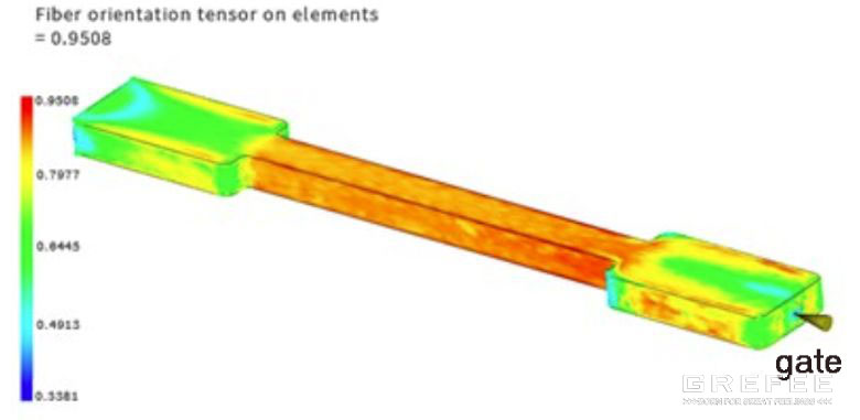
3. use mold flow analysis software to prevent the warpage
Using the mold flow analysis software can accurately predict the tendency of the product warpage before the mold opening, and carry out the optimized design to reduce the warpage. This is a developed and effective method.
▲process of preventing warping by using mold flow analysis software
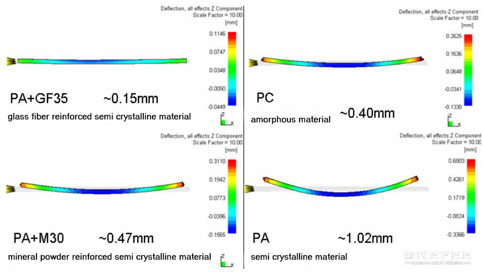
Plastic material selection
The shrinkage rate, flowability, fiberglass content, temperature resistance of the plastic materials will lead to warpage. If other conditions are same, the warpage in different plastic rubber materials are different. The semi crystalline plastic is more easily to have warpage compared to amorphous plastic. The warpage of glass fiber reinforced plastics is smaller than that of non glass fiber reinforced plastics in the direction of melt flow. According to the application requirements, it is better to use plastic materials with low warpage possibility in situations require high dimension accuracy.
Design plastic part
1 .even wall thickness
Uneven wall thickness is the fundamental reason for the warpage. Thus, in designing the plastic rubber part, making an even wall thickness as far as possible.
2. Smooth transition at uneven wall thickness area
Smooth transition is needed at uneven wall thickness
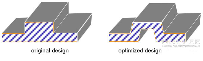
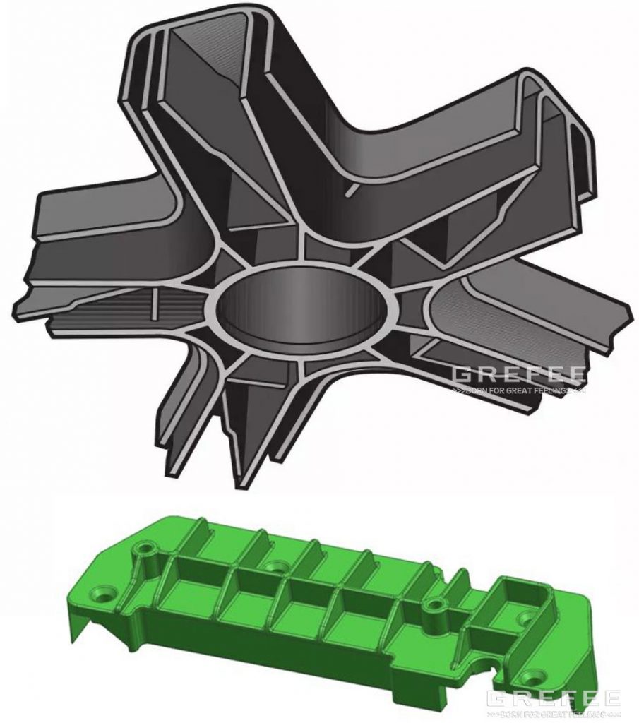
3 .Hollowed out design shall be used where the wall thickness is too thick
For areas with thick wall thickness in the part, the hollow design is required to make an even wall thickness.

4 .Mold release obliquity should be as large as possible
The mold release obliquity should be as large as possible to avoid the warpage due to the mold sticking during the ejection.
- Common draft angle: above 1~2 degrees
- Appearance surface: to increase the draft angle
- Draft angle: 0.5 degrees
- Appearance surface: increase the draft angle
- Undercut surface: depends on the undercut specification
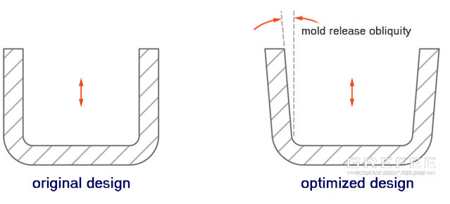
▲ mold release obliquity
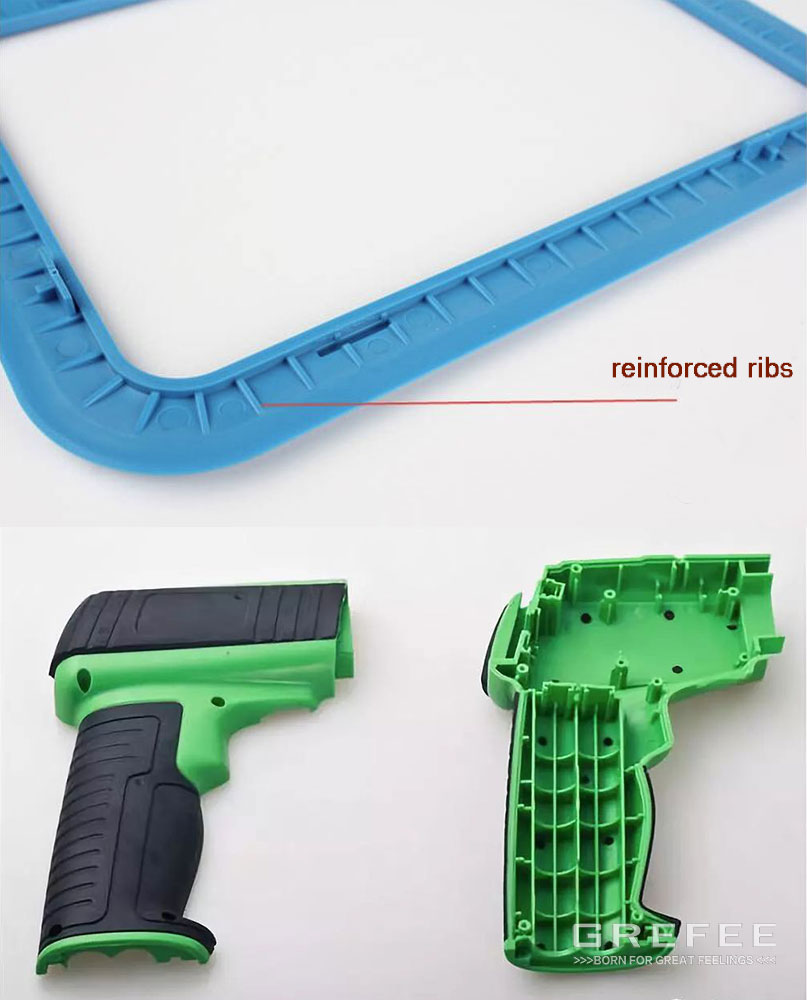
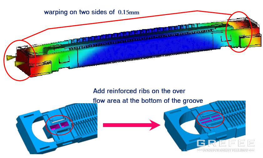
5. Part strength enhancement
For the weakness of the plastic part structure, we should to increase the strength by adding the reinforced ribs to avoid the deformation during the ejection.
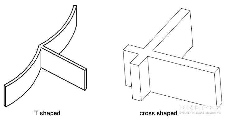
6. Appropriately design the structure of plastic parts
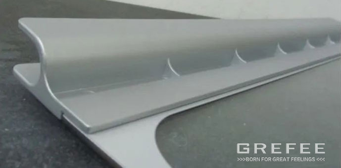
1 .L-shaped structure changed to T-shaped structure

2. T shaped structure changed to crossed structure
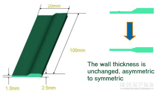
3. Maintain the wall thickness unchanged when the wall thickness is uneven, and change it to symmetric form.
7. Correct the warpage through the assembly design
When the warpage is inevitable or the cost to avoid the warpage is high, try to put the part into the product structure, and to reduce the warpage by the design of other components.
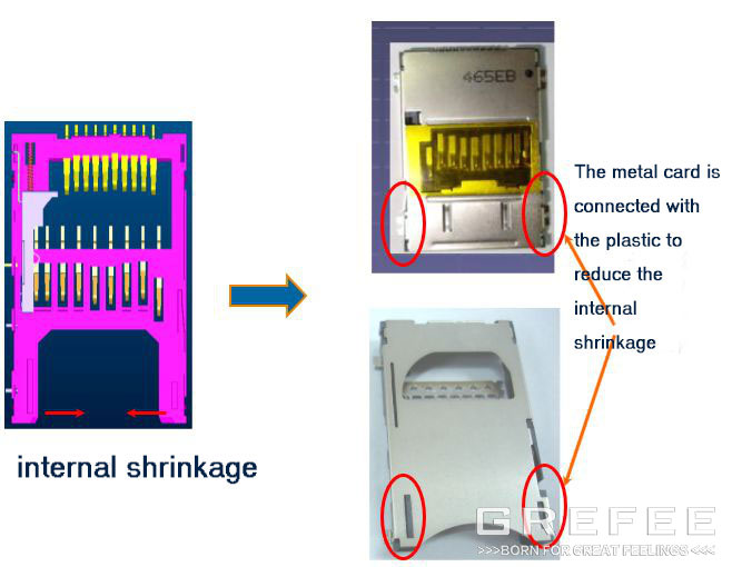
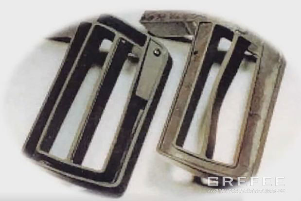
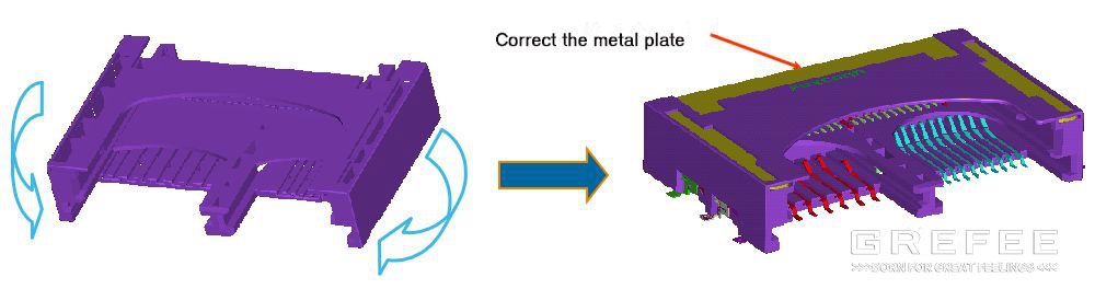
8 .Correct the warpage by adding metal plates
Adding the metal plates into the plastic part to correct the warpage. The disadvantage of it is high cost, which is the last solution, not recommended.
Mold structure
The mold structure includes three parts, pouring system, cooling system, and ejection system, which exert a large impact on the warpage of parts.
1. Appropriate pouring system
The position, structure, and number of the gate of the injection molding mold affect the filing status inside the mold cavity, leading to the warpage of the part.
(1). Relationship between flow length ratio and warpage
During the filling, the melt flow inside the mold cavity. In most cases, the mold temperature of the mold cavity wall is lower than the melting point of the plastic. Thus, the cooling should start as soon as the melt enters into the mold cavity, and the melt that contacts the mold wall will construct a unmovable shell (condensing layer), whereas the inner area is till hot melt (flowing layer).
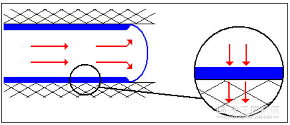
(2). The longer the flow length, the larger the internal stress resulting from the flow and shrinkage between the condensing layer and central flowing layer. By contract, the short the flow length, the shorten the time for flowing from the gate to the end of the workpiece. The thinner the condensing layer, the lower the internal stress, the smaller the warpage. The longer the flow length of the melt, the higher the possibility of generating the internal stress. Thus, for plastic part with long flow length and large area, the number of gate should be incensed to reduce the orientated stress effectively and avoid the warpage. However, too many gates will lead to welding marks.
2. relationship between flow equilibrium and warpage
filling pattern refers to the flow status changing as the time from the transportation system to mold cavity. The filling mode has a determined effect to the warpage of part. The ideal filling process is that the melt flows to each corner of the mold cavity at the fixed melt front velocity, MFV, otherwise, the area that is filled firstly will be overflow due to the over filling. Moreover, if the cavity is filled with varying melt wavefront velocity, the molecular chain or fiber orientation will be changed.
3. Appropriately design the pouring system
Appropriate pouring system design is beneficial to reducing the warpage.
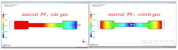
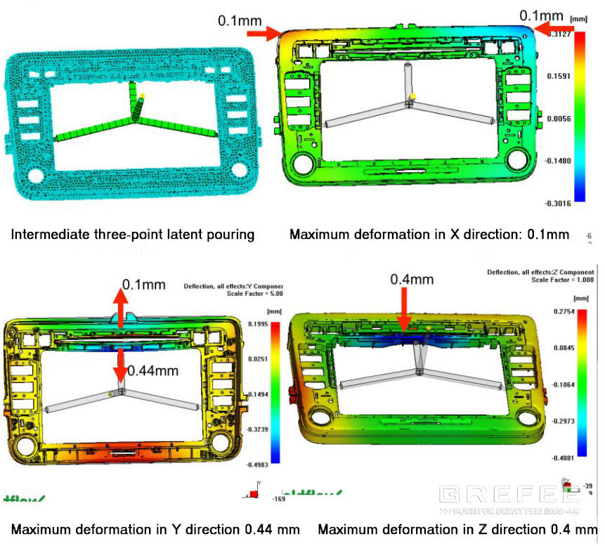
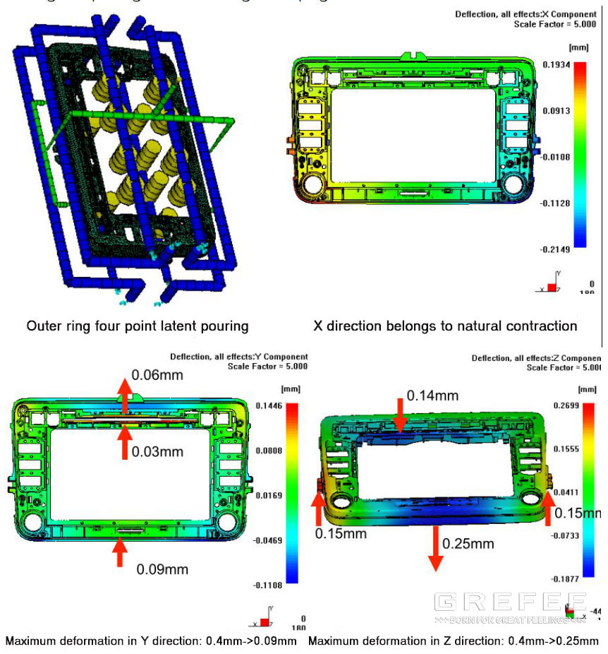
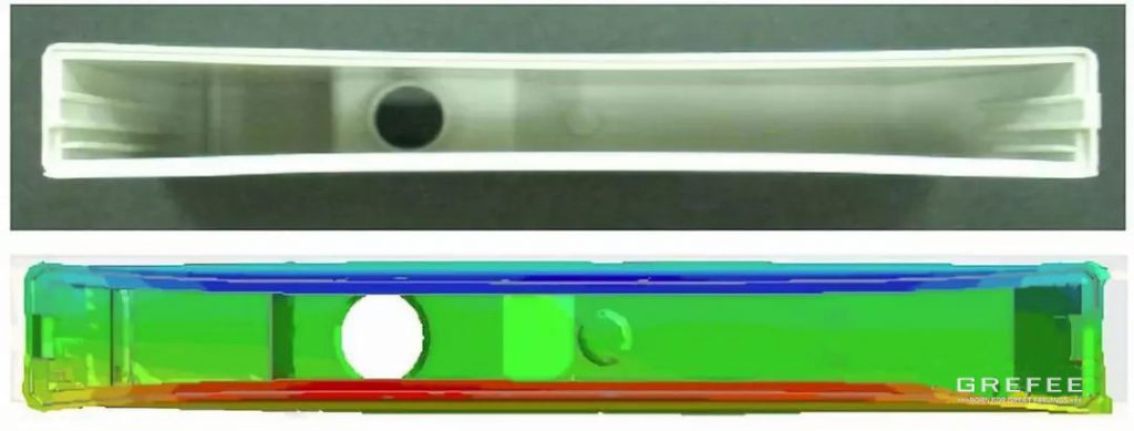
The gate should be designed on the thickest wall thickness area to reduce the injection molding pressure, holding pressure, and pressure maintaining time, to reduce the internal stress. When the gate is designed at the thin wall area, increase the wall thickness of the gate to reduce the orientated stress around the gate. 2) the longer the melt flow length inside the cavity, the higher the possibility of generating the orientated stress. Hence, there should be more gates for parts with thick wall thickness, long flow length and large area because it can reduce the orientated stress and avoid warpage. 3) short and thick runners can reduce the pressure and temperature loss, which reduces the injection pressure and cooling speed correspondingly, and further lowers the orientated stress and cooling pressure. 4) the design of the runners should be balanced to balance the injection of each gate. Inappropriate runner design will lead to unbalanced material filling. Overfilling some local areas will generate larger shear pressure and generate stress due to the large holding pressure. For example, the figure below shows the car audio panel. By optimizing the pouring system, the warpage can be reduced.
Product size: 227.5 × one hundred and thirty-six point nine × 22.7mm basic wall thickness: 2.5mm forming material: pc+abs bayblend T65 Bayer
2 .Appropriate cooling system
The distribution of the cooling circuit should be uniform to allow the area close to or far away the gate, thick and thin wall thickness area to cool uniformly and slowly to reduce the internal stress
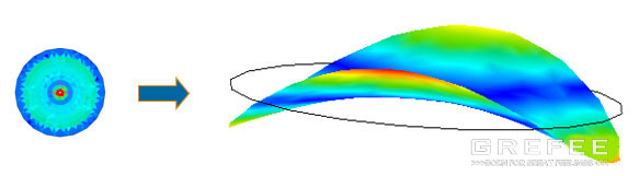
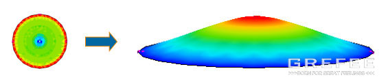
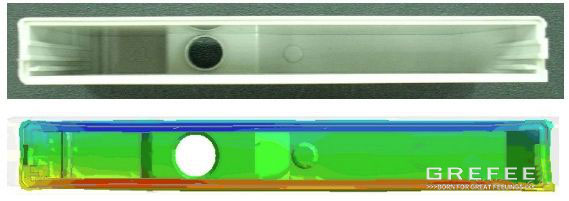
(1). Different mold temperatures cause different warpage
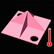
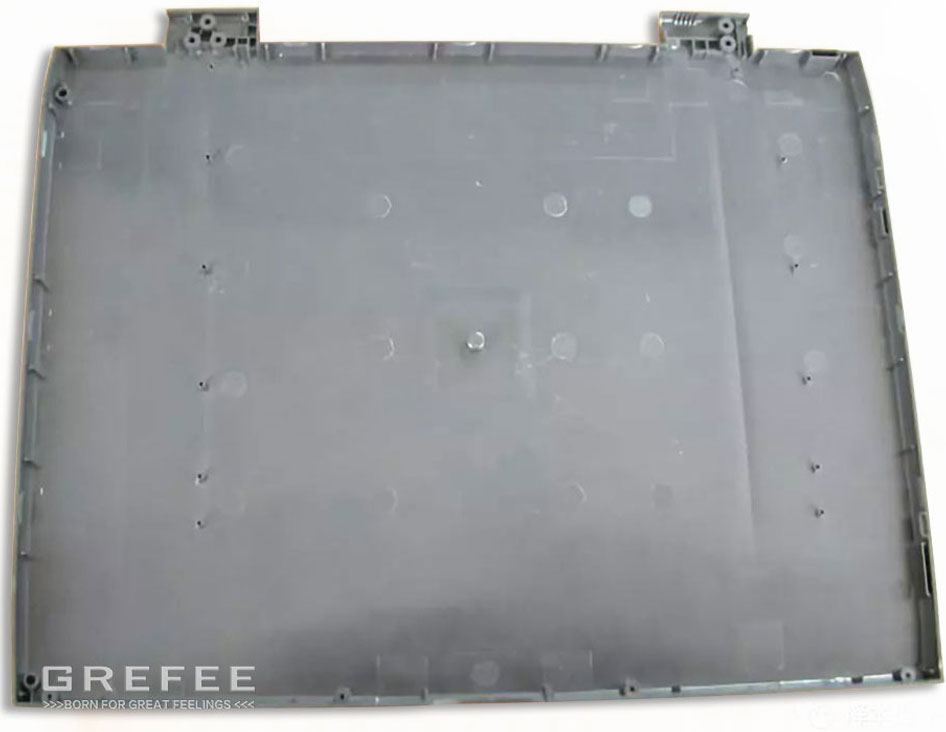
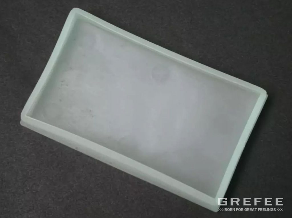
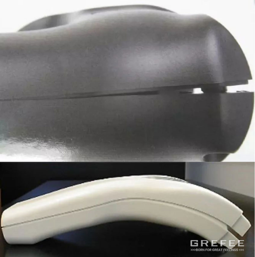
The temperature of two sides of the plastic part will lead to warpage.
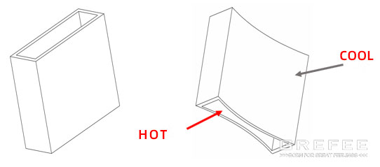
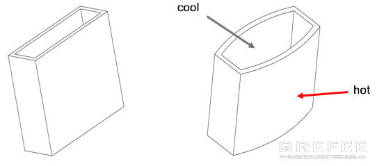
▲When forming the deep box shaped plastic part, if the internal area is over cooled, the plastic parts will be deformed as shown in the figure above after the plastic parts are taken out with high-speed cold water inside.
(2). Optimize the cooling circuit — scenario 1
Through optimizing the cooling circuit, each part of plastic part will be cooled at the same time, and the warpage can be reduced.
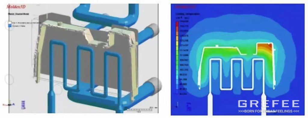
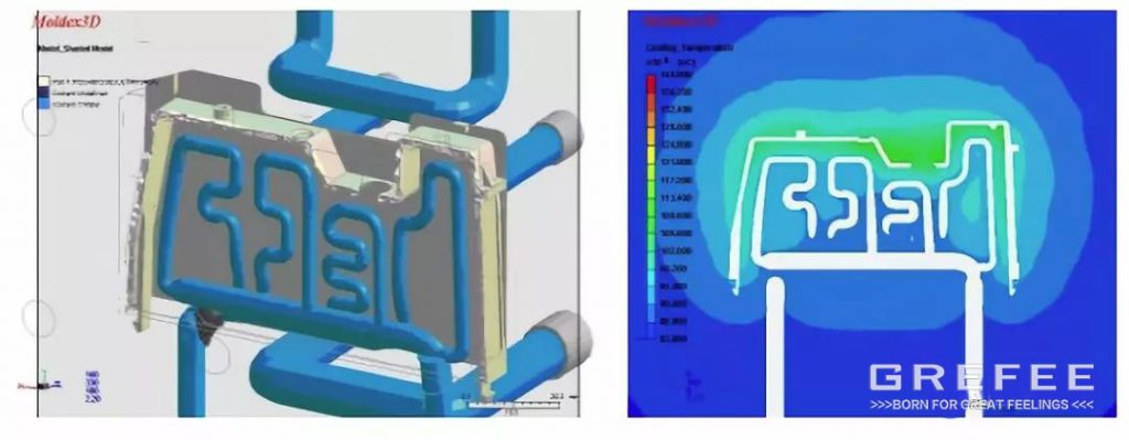
(3). optimized cooling circuit — scenario 2
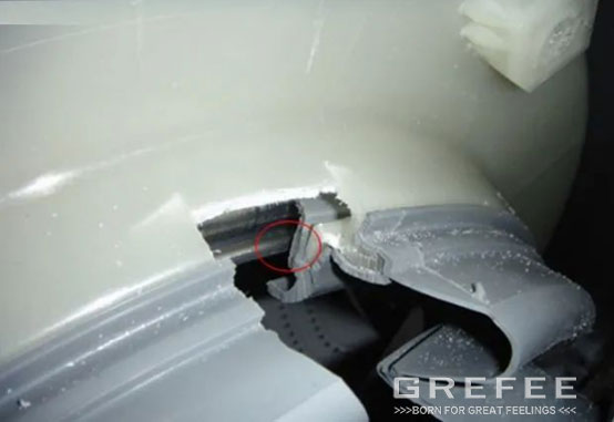
3.appropriate ejection system
The design of the ejection system also determines the warpage of the plastic part. there are many factors will lead to warpage, such as the unbalanced mold release force, unbalanced pushing structure or inappropriate mold release ejection area. Demoulding improvements to prevent ejection deformation: balance the jacking force, carefully polish the new side, increase the demoulding angle, and arrange the ejector rod at the place with large demoulding resistance, such as the stiffener and pillar.
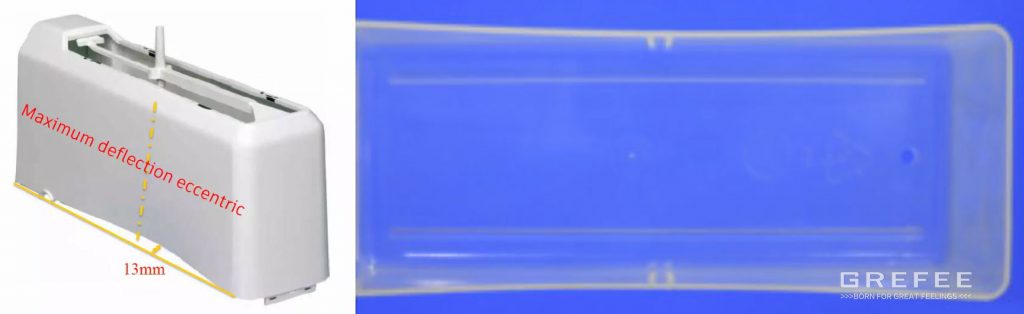
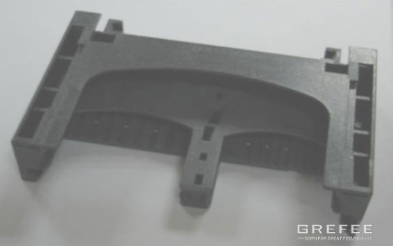
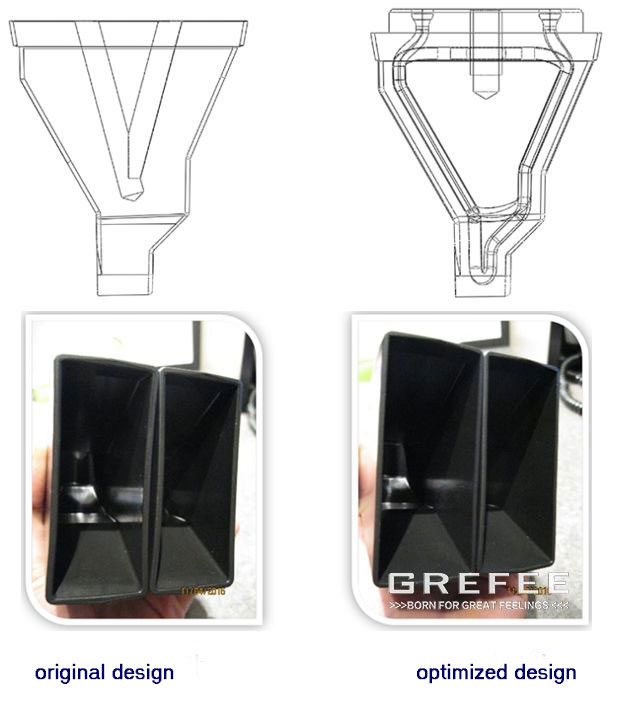
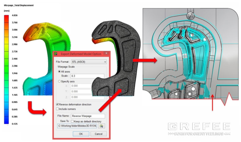
4. pre-compensation of deformation
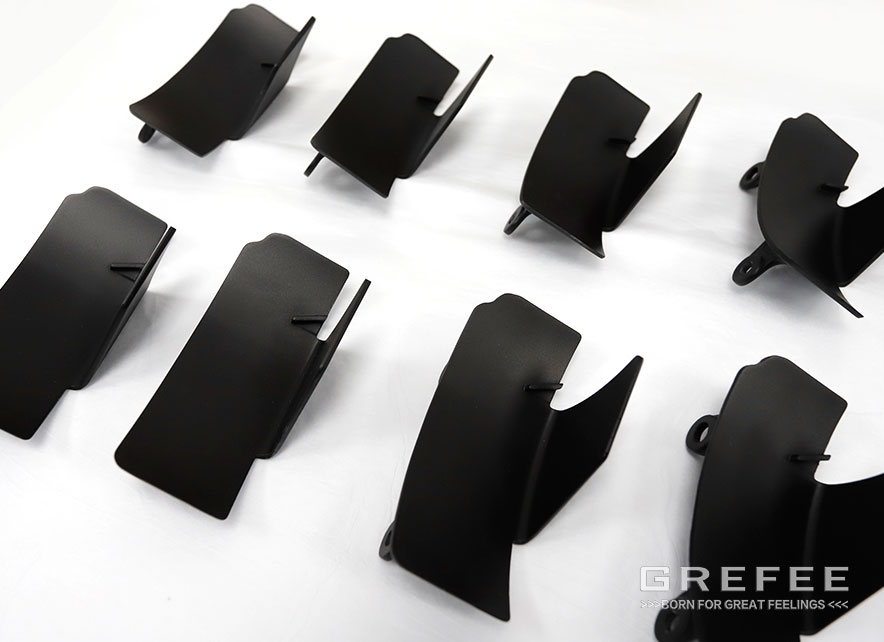
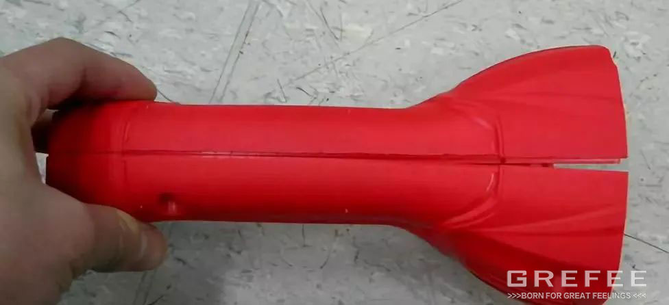
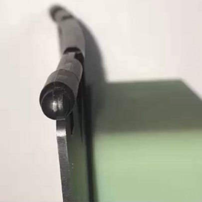
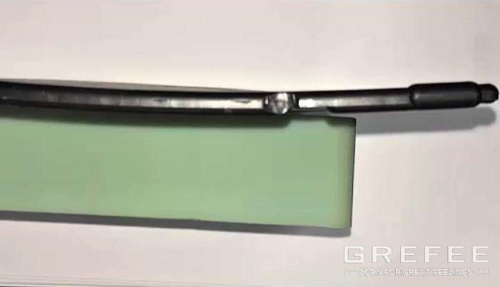
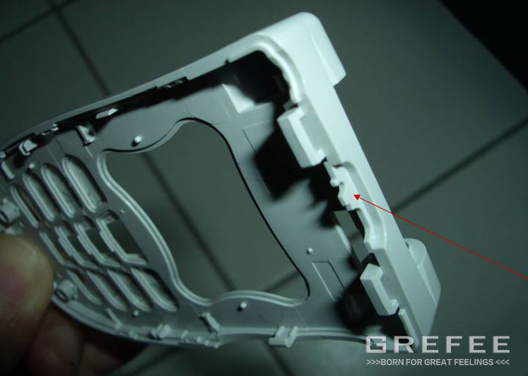
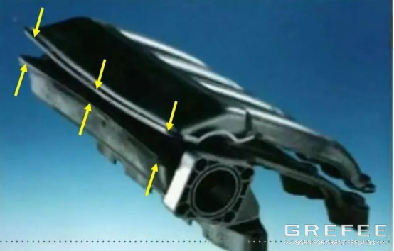
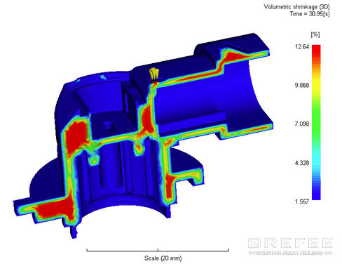
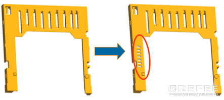
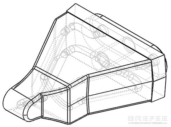
The pre-compensation of deformation applies a special pre-deformation (reverse deformation) on the structure and size of the corresponding mold parts according to the product deformation analyzed and predicted by the mold flow analysis software or the deformation of the plastic parts in the actual molding to compensate the deformation in the molding, reduce the warpage deformation, and improve the dimensional accuracy. The plastic buckle as shown in the figure is severely deformed at the position indicated by the red arrow. However, conventional methods, such as gate position adjustment and cooling system optimization can not solve this problem.
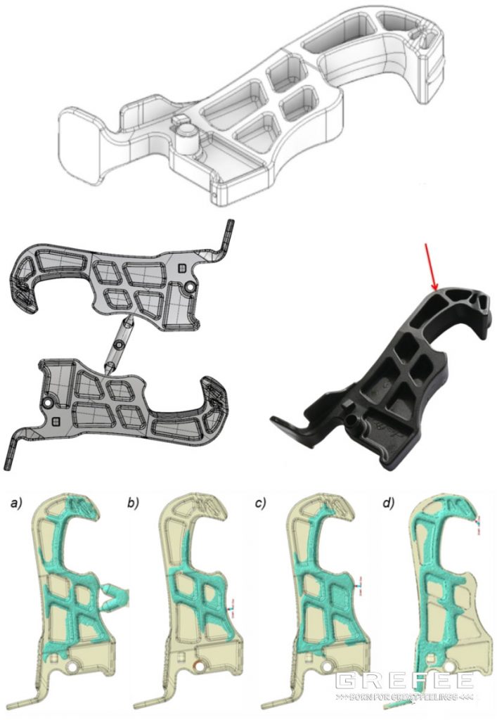
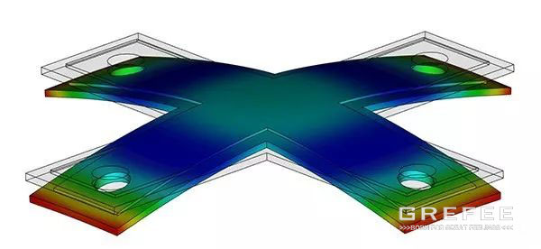
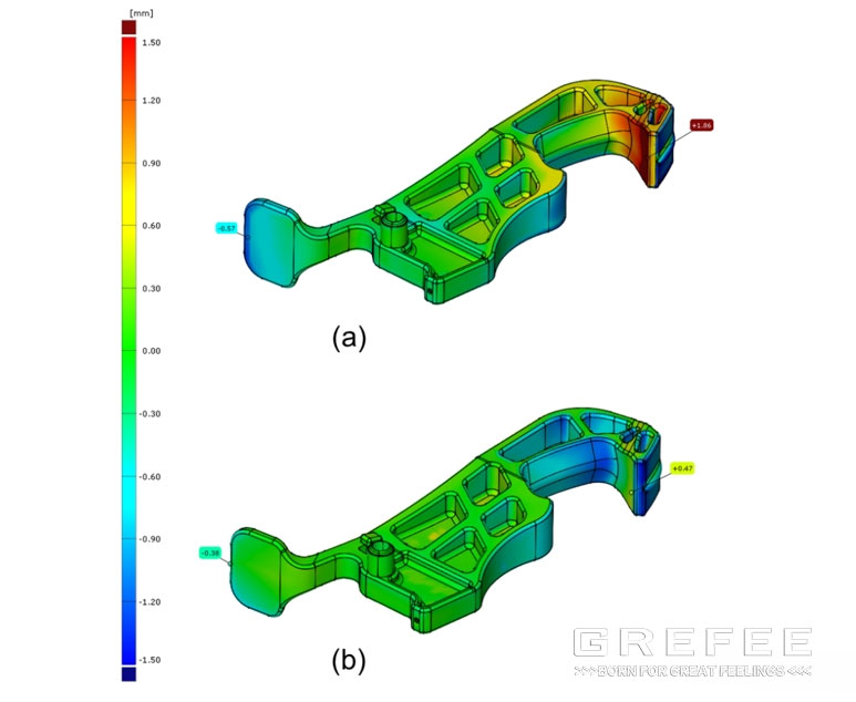
Through the pre-compensation of the deformation, exert a certain pre-deformation at the opposite direction of mold. Shown as the figure, grey represents the original mold structure, blue is the pre-deformation structure at the opposite direction.
After the pre-compensation of the deformation, the actual deformed amount of the plastic part reduced from 1.86mm to 0.47mm.
Injection molding process
To reduce the warpage of the plastic parts, we can start from the four aspects of the injection molding coefficients:
1 .Reduce the injection pressure and velocity
High injection pressure and flow velocity will generate high shear velocity and internal stress, leading to warpage. Lower injection pressure can lower the orientation of the molecular of the plastic materials and internal stress to reduce its internal stress and warpage, injection pressure and velocity to the lowest within the allowed range.
2. adjust the holding pressure and holding time.
High holding pressure is due to the high flow residual stress resulting from the solidified feeding, and the stress is easy to release, causing the plastic parts to warp. Too low holding pressure will lead to the backflow occur near the gate, which will not only form the flow residual shear stress, but also form a large difference in volume shrinkage, resulting in high residual tensile and compressive stress, as well as the warpage and deformation of plastic parts. Short holding time is short make the backflow occur near the gate when the screw retreats, resulting in large residual stress. Hence, the holding pressure should be moderate, and the holding time should be extended until the gate solidifies to reduce the residual stress.
3 .adjust the mold temperature.
The mold temperature is low and the residual shear stress is large will easily cause warp and deform if there is not enough time to release the residual stress. Increasing the mold temperature reduces warpage. But not low temperature is not far enough. For some shapes, low temperature will increase the temperature difference between the mold cavity and the mold core, and then causes deformation. On top of that, when the mold temperature is lower than the service environment temperature of plastic parts, deformation or size change will occur due to post shrinkage.
Therefore, in terms of the mold temperature, the fundamental is not the temperature, but the uniform temperature (equilibrium) including the core cooling to achieve uniform shrinkage.
4 .Cooling time adjustment
Since the shape holding time of the plastic part is prolonged in the mold cavity, increase the cooling time in many situations will reduce the deformation.
However, it is conversely for some shapes, since the clamping of the mold core and some other reasons, increase the cooling time will lead to poor mold release and cause deformation, which is not homogeneous.
Conclusion
The warpage of plastic parts is always a tough problem. If the injection molding parts manufacturers know how to concur it with a structural system, which includes plastic material, plastic part design, mold structure, and injection molding process combined with the understanding of uneven shrinkage, it is no longer a difficulty.
MORE BOLG
Insert mold in injection mold service
What are advantages and disadvantages of Zinc alloy and Aluminum alloy?
Inspection standards for injection molded partappearance
How to judge the quality of your plastic products?
Inspection standards for CNC machining
To ensure that your products are 100% qualified
Categories

Try GREFEE now,for free
We keep your uploaded files confidential and secure.