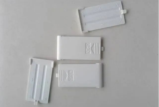
Plastic part art line design

Posted on :Feb 21 , 2023 , By GREFEE

1 .Definition of art line
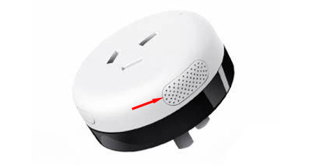
Process art lines commonly found on plastic products that serve structural, technological or decorative purposes. From a distance, they look like a line and are therefore referred to as aesthetic lines, ugliness hiding lines or decorative lines. There are various names for these lines, but they will be referred to as aesthetic lines in the following text.”
2.Why is an art line necessary? What is the role of an art line?
1. Structure
1)Even crevice
When the product’s upper and lower shells are assembled, a process art line is necessary to avoid defects in appearance due to uneven gaps caused by the edge contour of the shell being too large or deformed during the injection molding process. The design guideline provides a gap visually to reduce unevenness, the wider the gap of the design guideline, the less noticeable the uneven visual perception will be.

2) Reduce hand feeling
When the product’s upper and lower shells are assembled, it reduces the hand feeling caused by the great assembly section difference which generated due to the deformation of shell during injection molding.
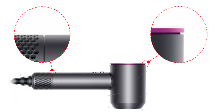
Especially when the parting surface is curved, the appearance dimension accuracy is more hard to control. Adding a process art line can lower the requirements for mold accuracy when the appearance condition allows.
Why design guideline can reduce hand feeling?
Process art line provides the crevices allowing a larger angle α between fingers and shell corners. The horizontal force on the fingers from the sharp angle of the casing decreases as α increases.

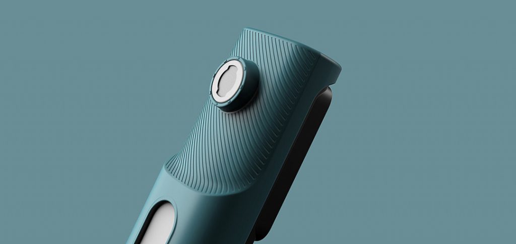
In addition, the inverted fillet angle (inverted fillet or chamfer) that we know actually means to increase the contact area between fingers and objects to reduce the pressure on fingers and hand felling. The pic below uses the inverted fillet design.
2. Process role:
1)Oil splashing prevention:
When the same surface requires to be painted by different colors, the process art lines can separate the two connected surfaces for a different color painting to prevent the a different color oil from splashing on the other sides. At the same time, it can store the accumulated oil that may occur in the design slots. So, it looks like a straight line from outside.
If there is no design art lines, since it is difficult to achieve a seamless fit at the color boundary of the mold (the mold accuracy is extremely high), the paint will splash or penetrate into another surface and cause the boundary line of two colors are not straight and clear but is similar to serrated or maybe oil accumulation at the boundary.

2) Covering up defects:
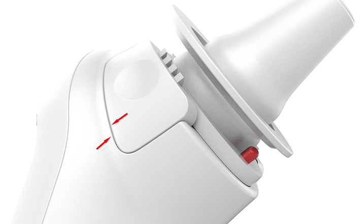
When the appearance of the product is out of place on the mold, design lines can be placed at the location of the out-of-place line to hide the unsightly out-of-place line within the design line.
When the appearance of the product is the insert, design lines can be placed at the position of the insert line to hide the unsightly insert line within the design line. (This is common in some ODM manufacturers’ frame logos, where different brands only replace the inserts in this area, or two plastic parts have the same structure except for the inserts. This approach can avoid reopening the mold.)

3. Decoration:
Design lines are added to some large surfaces to avoid appearing stiff and to increase the sense of hierarchy and enhance the visual effect, based on an aesthetic design.
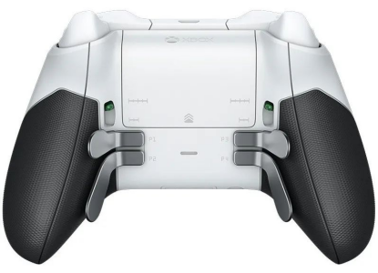
Decorative design lines are also widely used for functional requirements, such as anti-slip design lines for handheld products, and raised design lines for battery covers to facilitate opening, etc.
3.Classification of process art lines
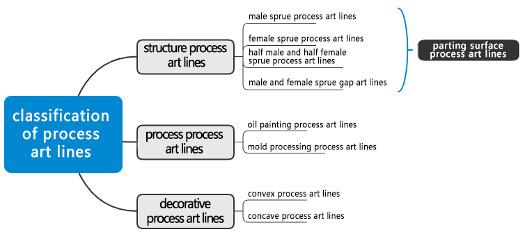
The types of process art lines can be categorized according to their function.
1. Structural Graphic Design Line
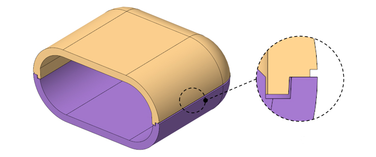
This type of graphic design line is designed at the parting surface where two parts fit together, so it is also called a parting surface graphic design line. This is also where the sprue is located, so it is also called a sprue graphic design line. In theory, parting surface graphic design lines are not necessary, but in practice, due to the lack of precision in mold processing, deformation of the rubber shell, and misalignment during assembly, unavoidable gaps can form in the appearance. At this time, graphic design lines have to be designed to remedy the defects in the appearance.
There are several types of products that require graphic design lines to be designed on the parting surface:
1)For products with larger dimensions, it is difficult to control the dimensional tolerance within a reasonable range, both in the product structure and in the mold. In order to reduce the obvious gap between the upper and lower shells, parting surface graphic design lines should be designed.
2) If the structural strength of the product is not enough and it is prone to deformation, it may be difficult to control the gap between the parting surface during assembly. To prevent serious injuries, parting surface graphic design lines should be designed.
3) If the level of mold processing in the mold factory is not high and the precision of mold making is not enough, parting surface graphic design lines can be designed within the allowed range of appearance to prevent defects such as gaps and uneven seams caused by mold processing problems.

a) Male Sprue process art Line and Female Sprue art line are respectively located at the male and female sprues. The appearance of both types is generally acceptable, and mold processing is relatively simple. However, when the wall thickness of the shell is thin, designing the graphic design line on the female sprue may make it thinner and easier to cause other injection molding problems, which should be noted.
b) Half Male-Female Sprue art line is cut in half on the male and female sprues, which is more aesthetically pleasing. However, mold processing is more complex compared to the previous two types (the groove width should not be too small, otherwise, after the upper and lower shells are evenly divided, the groove will be smaller and the mold processing will be difficult).
c) Male-Female Sprue Gap Art Line is formed directly through the gap between the male and female sprues. Because the groove of the process art line is too deep, the appearance is less attractive, but mold processing is the simplest (if there is no special requirement for appearance, this design can be chosen to reduce the difficulty of mold processing).
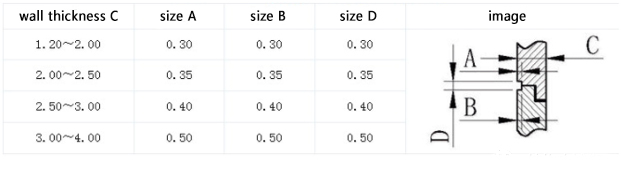
Recommended structural dimensions of graphic design lines on the parting line.
2. Process design lines:
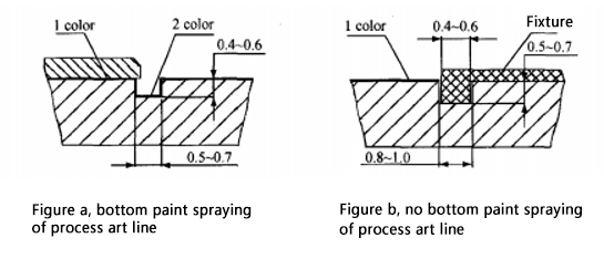
Oil painting process art line: The product surface is painted with two colors of paint to separate the two colors with a separating groove. A fixture mask is used to meet the requirements of two-color spraying. The separating groove is often designed as a recessed structure, and the size is designed according to the precision of the shell and fixture, and the spraying requirements. If the precision of the shell and fixture is high, the art line can be appropriately reduced in size. Generally, the shell is designed according to the spraying requirements. The following principles are commonly used:
a). Due to the paint sprayed at the bottom of the art line, the coating groove will have a significant air flow rebound phenomenon. Grooves that are too deep or too narrow will reduce the thickness of the coating adhesion film, resulting in poor uniformity, especially for colors with poor hiding power. Therefore, according to experience, the width of the spray design graphic line is 0.5-0.7mm, and the depth is 0.4-0.6mm, as shown in Figure (a).
b). The bottom of the art line is not sprayed with paint. The width of the process art line is 0.8-1.0mm, and the depth is 0.6-0.8mm. If the groove width is too narrow, it will reduce the strength of the fixture embedding site, and at the same time increase the risk of not being able to embed due to changes in the molded size of the fixture embedding part, as shown in Figure (b).
2). Aesthetic Lines in Molding Process
The slot that prevent the occurrence of flashes and welding lines in the mold demarcation. It is mainly applied into the mold slides or replaceable inserts as the accuracy modification cannot be 100% perfect at these places. Flashes and welding lines easily occurs at these areas during injection molding, but aesthetic lines can hide these defects.
This kind of aesthetic lines are normally depressed, size: 0.50mm (width) x 0.50mm (depth). The aesthetic lines for products having higher accuracy requirements can be relative smaller. For the sake of simple processing, convex is also acceptable if it fits the appearance.
3. Decorative aesthetic lines
The decorative aesthetic lines are used for the ornamentation and decoration for product modeling. Normally, there is a depressed slot of which the size, shape and distribution are related to the appearance and detail modification of the whole product. The value of the width and depth of decorative aesthetic lines are not that strict. Considering the convenience of mold processing, it depends on the condition of slots. Typically 1.0mm x 0.5mm, 0.8mm x 0.5mm, 0.5mm x 0.5mm, 0.3mm x 0.3mm, etc.
Dos and don’ts of designing guidelines
The upper and lower shell gap problem cannot be effectively fixed after the design of aesthetic lines and thus there are surface scraping and bottom scraping . When designing, surface scraping is normally used and the outer shell size is 0.1~0.15 bigger than the bottom.

2. When designing the cosmetic lines, the wider the slot width, the shallower the depth, the easier the mold is to process. So, within the constraints of appearance, the slot width should be designed as wide as possible and the depth should be shallow.
3. The decorative design slot section should not be designed as a rectangle as much as possible as the rectangular slot bottom is prone to form dead angles and just accumulation. It should be rounded or designed as a trapezoid for easier dust removal.
MORE BOLG
Insert mold in injection mold service
What are advantages and disadvantages of Zinc alloy and Aluminum alloy?
Inspection standards for injection molded partappearance
How to judge the quality of your plastic products?
Inspection standards for CNC machining
To ensure that your products are 100% qualified
Categories

Try GREFEE now,for free
We keep your uploaded files confidential and secure.