How to select the right hot runner types for injection molding dies

Posted on : Apr18, 2022 By GREFEE
The hot runner technology brings a revolutionary change into the mold market. More and more customers choose hot runners. The spread of this technology increases the pass rates of production and quality of products. It also minimizes the deformation issues of the products’ appearance.
Meanwhile, it raises the production rates and achieves automation production, which expands the application range of the injection molding technique. With more programmable features, it accurately adjusts the injection molding technique. Besides, it improves the consistency of products and the balance of injection.
It can shorten the cycle time effectively, which suits for molds with multi-cavity.
Although hot runners have more evident advantages than cold runners, it still has some inevitable shortages. As hot runners are more complex, their maintenance cost is higher. It is likely to damage the accessories of hot runners if not being used properly, but cold runners surpass hot runners on this point. Its maintenance cost is low, and cycle time is shorter. Moreover, hot runners are likely to have leakage issues, but this does not affect their application performance.
Why hot runners? In general, with the development of the hot runner technology, we will overcome the shortages, and this technique will be used more with its excellent advantages.
GREFEE works with first-class hot runner suppliers, such as MOLD-MASTERS, INCOE, HASCOSYNVENTIVE, DME, etc. We are experts in the field of molds with multi-cavity. Our proficiency in this field makes us the first choice of many customers.
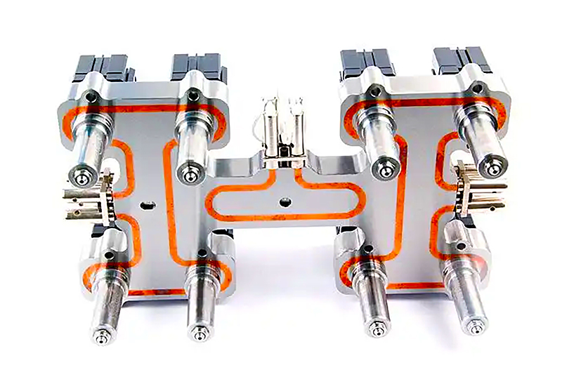
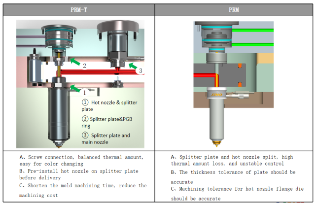
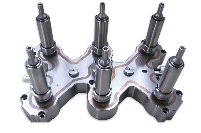
Structure of hot runners and name of components
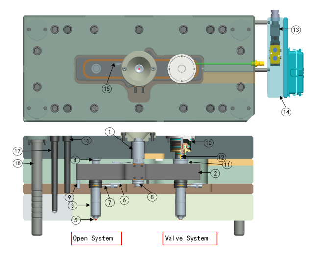
1.Main nozzle—connect the barrel to hot runners (splitter plate)
2.Splitter plate —split flow
3.Hot nozzle—connect the splitter plate to the products
4.Insulated meson—insulation, pressure heat nozzle, prevent leakage from the joint of oof splitter and hot nozzles.
5.Nozzle tip—select different types of nozzle according to the inlet surface.
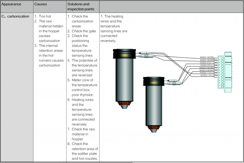
6.Temperature sensing lines —temperature sensing lines control the temperature
7.Temperature sensing lines—sensing nozzle temperature
8.Fixed splitter plate screws—fixed splitter plate
9.Centre pin—position the center of the splitter plate
10.Anti rotation pin—prevent the splitter from moving and deviating
11.Gas cylinder —drive valve needle
12.Valve needle sleeve gland—pre-load the valve needle sleeve and hot nozzles, prevent the leakage from the joint of the splitter plate and hot nozzle
13.Valve pin—control the switch of the material
14.Solenoid valve—drive valve needle
15.Junction box—fix the socket and hidden wires
16.Temperature sensing lines of splitter plate—sense the temperature of splitter plate.
17.B2 screw—prevent deformation of mold and the leakage of the hot runner system
18.B1 screw—Locking and fix the hot runner system(cavity)
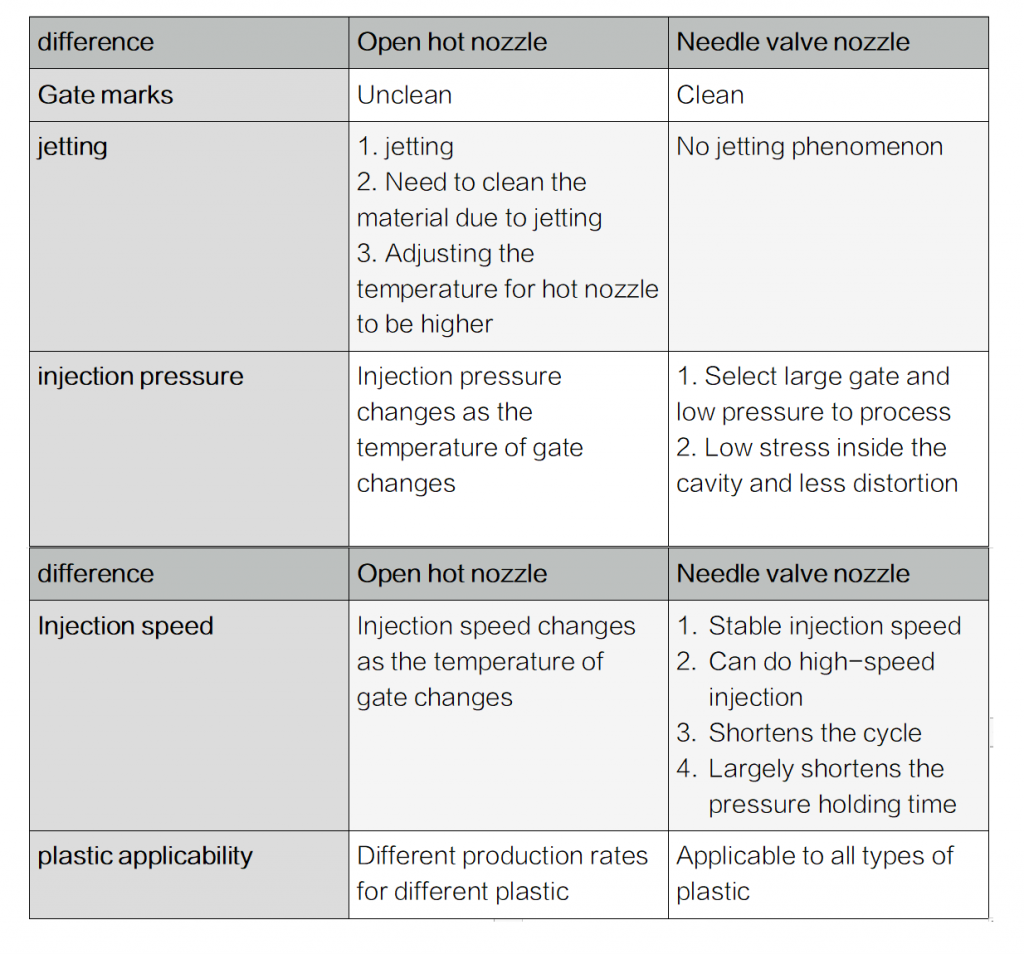
Difference of the valve needle hot runner system and open hot runner system:
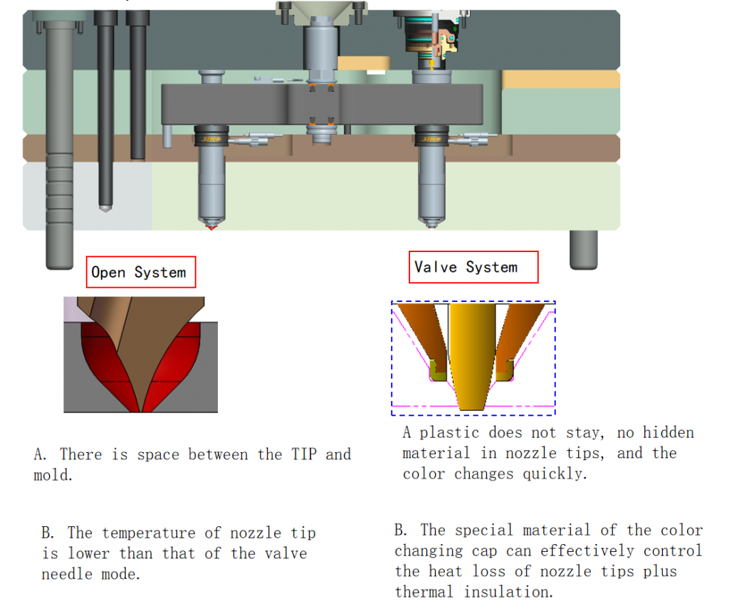
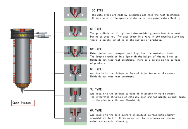
Open hot nozzle:
Needle valve hot nozzle:
Comparison of characteristics between needle valve nozzle and open hot nozzle
Characteristics and using effects of needle valve system
- After mold clamping, the needle valve action immediately, and the gate opens immediately. The injection pressure transmits into the mold cavity. In the holding pressure process, the gate closes, which shortens the next injection time.
- When manufacturing the large-scale parts with multi-cavity and multi-gate, we can achieve the goal by merely controlling the movement of the needle valve.
- Also, we can adjust the injection amount of each cavity or can improve or move the welding marks.
- The needle valve system can enlarge the gate to achieve low-pressure molding and high-speed molding. This helps the cavity to fill successfully.
- The gate is cut by the needle for the perfect gate marks and the surface.
- A needle valve system can reduce the stress and distortion of parts to improve the quality of parts and extend the service life.
- A needle valve system can enlarge the gate, reduce the thickness of parts, and shorten the cooling time.
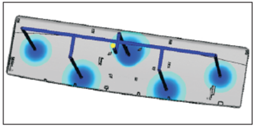
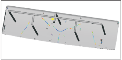
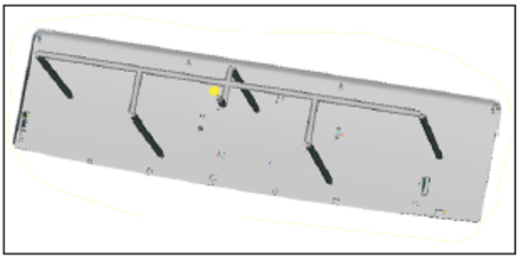
*Different injection amounts and shapes with multi-cavity or products have many points forming. There might have short molding issues or evident welding marks.
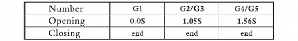
*To improve these issues, we can utilize the timing controller or the solenoid valve group to control the injection orders of each gate for better effects.
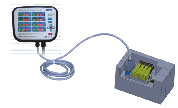
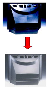
Adjusts welding line by the time controller

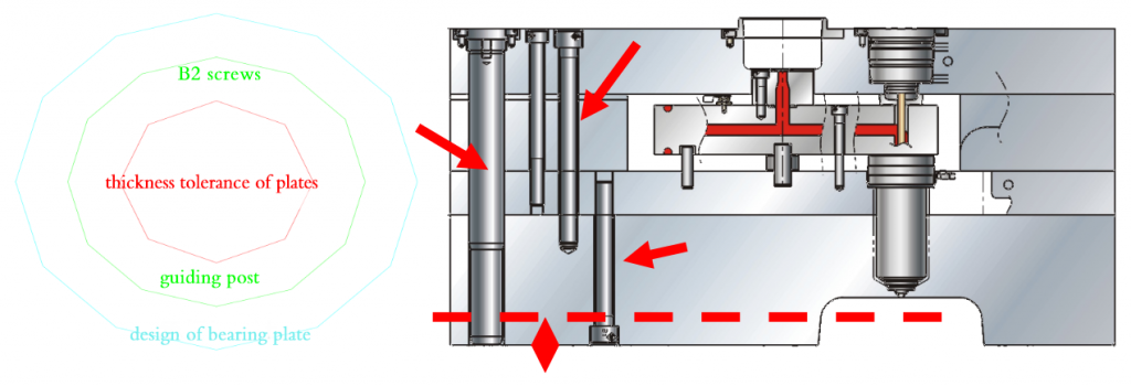
Notes and information needed for designing molds
- When the thickness of plate is not standard, there is leakage and other issues.
- B2 screws can prevent the hot runner system from leaking and other issues due to the deformation of molds.
- Adds guiding post between the cavity and hot runners, and the length of guide pin pillars should be 20mm longer than the hot nozzle.
- Requires the customers must use the bearing plate as using the hot runner system for the convenience of inspection and repairing.
- Asks the customers to try to provide the cavity core (core during inverse). Avoids interfere with the molds when designing the hot runners.
Needed plastic products information
The name and model of plastics
The forming and cooling temperature of plastic are different.
Cooling design around the gate area
Weight of products
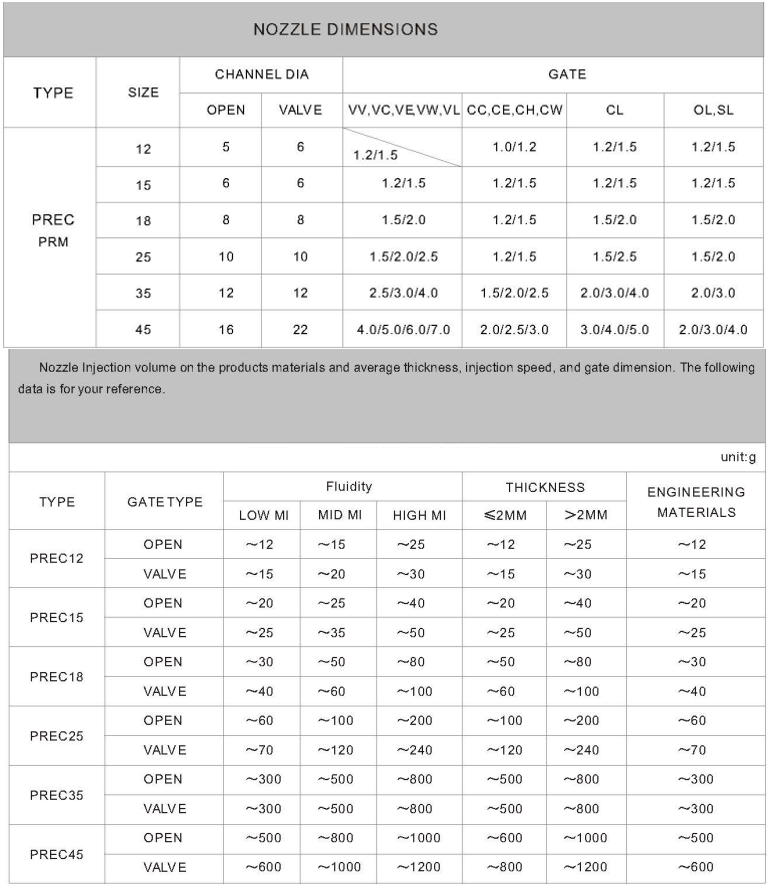
Size selection of hot nozzle
Design of splitter plate runner
Colour of products
If needs to change the color
If is transparent
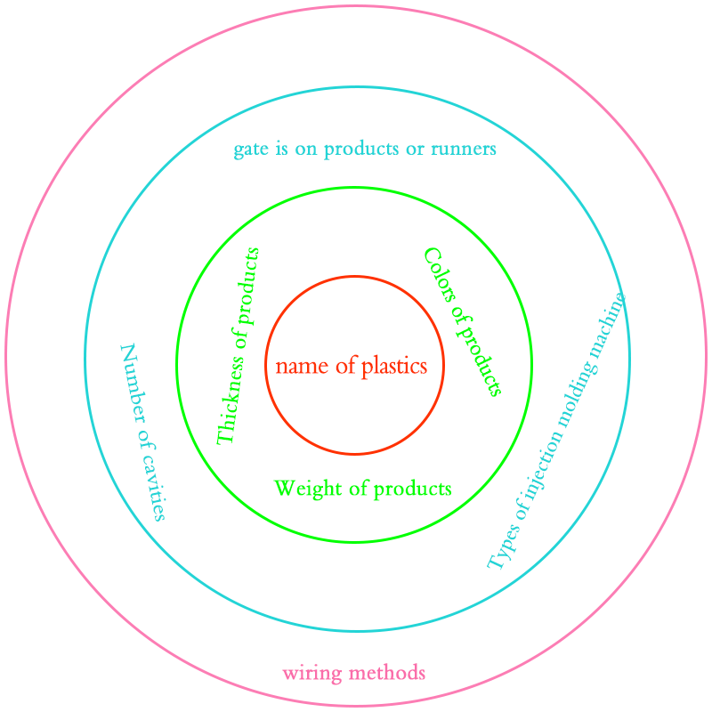
Thickness of products
Size of gate
If it is too thin, we need to consider enlarging the runners, enhancing the stiffness and other issues in high-speed injection.
Other information
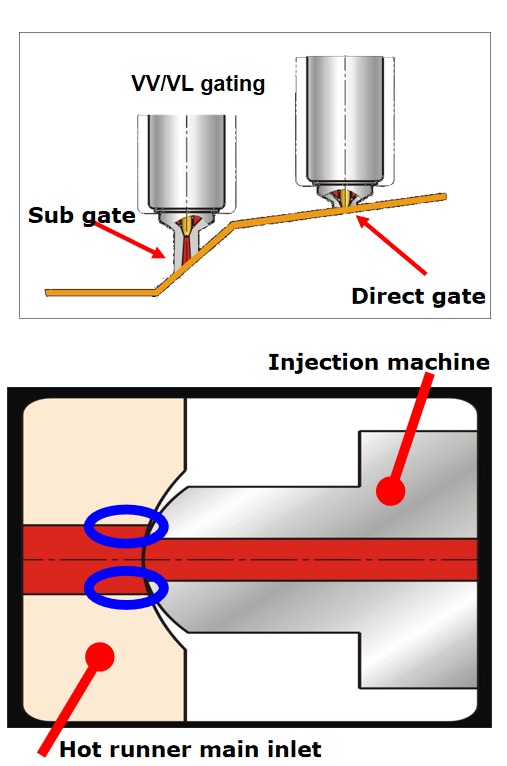
gate is on products or runners
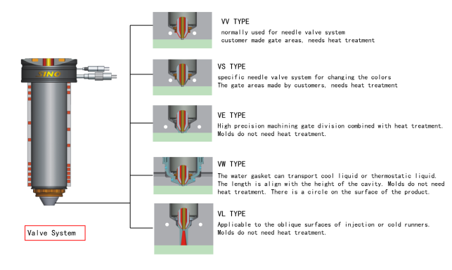
consider non-nozzle type (VALVE TYPE)
Runners, add the sprue puller when the thickness of products is less than the nozzle
Types of injection molding machine
High speed machine: enlarges runners, increases the number of B2 screws, hardens the mold base.
wiring methods
SINO, DME, MOLDMASTER
K TYPE OR J TYPE
injection molding machine
barrel caliber and SR
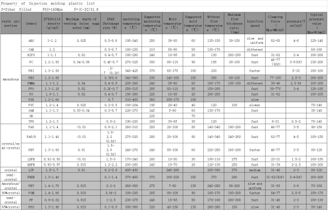
Temperature control advice for different types of plastic
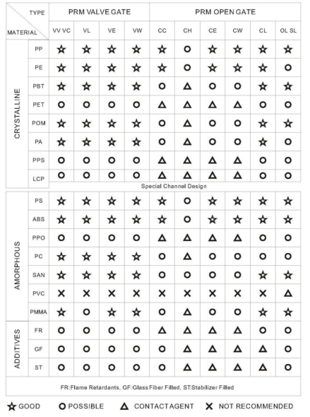
Property of Injection molding plastic list
How to select hot runner model?
Select the size of system and nozzle shape according to the resin, weight of products, and thickness.
Considerations of hot runner molds
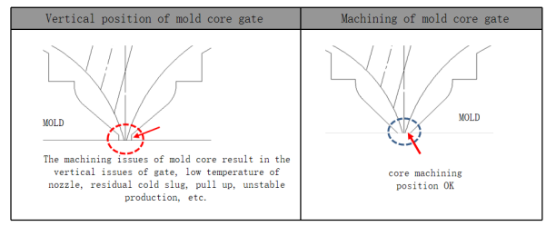
The nozzle of open system cannot have vertical position, otherwise will cause gellan gum or pull up.
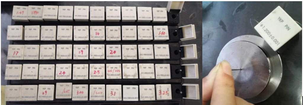
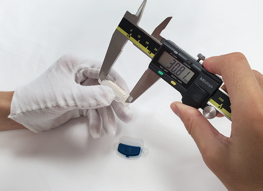
Inspect the gate: measure the size of gate by pass gauge before installing the hot nozzles.
- Avoid the unbalance injection due to the inconsistence in size
- Avoid jetting or wire drawing due to the too large size
- Avoid poor injection due to too small gate or high pressure due to insufficient injection.
How to deal with the most common glue leakage problem of hot runner?
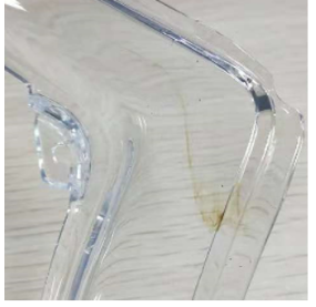
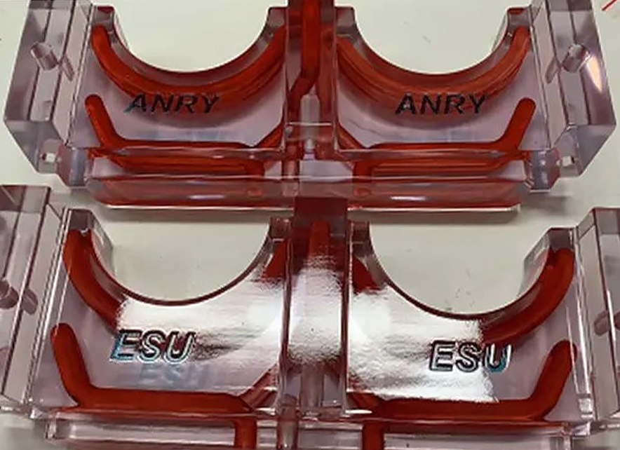
Trend: white, transparent, color change
Flow mark control methods:
How does open hot runners system control the flow marks?(listed by PC material)
1. Inspects if the material is complete dry
2.decreases the injection speed to avoid the air inside the mold cavity in time
3.increases the mold temperature to lower the cooling speed of melt in the cavity
4. Multi-stage injection control, slow injection at the areas with flow marks
5.reduces the cutting force of gate and enlarge the inlet.
6.cleans the jetting, cold slug at the gate (decreases the back pressure or increases the release position)
7. The temperature of hot open nozzle is low. When found flow marks, increases the temperature of hot nozzle(within the physical property range)
8. Cleans the surface of mold or increases the venting groove of mold.
9.adds cold slug well around the gate of cold runners
10. Checks if the water circuits is smooth, improves the balance of mold temperature.
Sharing of common problems in open hot runner production
The problem points are shared as follows:How to avoid nozzle block, unstable, burrs, and insufficient filling
1. The gate of the open hot runners is in the opening state, so it causes thermal loss. The temperature will be lower than that of other positions. If there is a nozzle block issue, which can fix by only increasing the temperature of the nozzle.
2. Higher temperature of hot nozzle will cause jetting or an unstable production cycle. The long-term stay will lead to jetting at the gate and a cold slug residual in the nozzle. Due to this, there might have a poor appearance and nozzle block in the next mold releasing process. Suggestion: increases the release position of strip storage and decrease the backpressure to avoid jetting. The injection speed should be from quick to slow, which enhances stability.
3. burrs generated due to the high injection speed. Slow injection speed results in insufficient injection and shrinkage. Suggestion: increase the mold temperature, or the water path close to the nozzle is connected to the mold temperature separately, which is used to maintain the temperature of the heat transfer gate, improve the fluidity of the plastic in the mold cavity, reduce the injection pressure speed, avoid sharp edge without lack of material, and reduce the cooling speed of the rubber in the mold cavity. Extends the holding pressure time, which helps products with sufficient filling and increases the stability of injection molding.
4. The gate position is poorly machined so that a vertical position is generated, which leads to low temperature in the gate, and the entry point goes up after holding pressure.
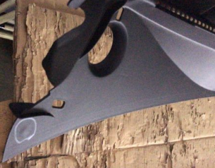
Successful cases of different types of open hot runner system
(1)Cause analysis and improvements of splay marks
1. Material is incomplete dry. The air generated during plasticization gets into the barrel, so there is air in injection, causing splay marks on the surface.
improvement methods:Take the reference to the actual temperature inside the barrel and evaluate if the time is enough for baking from adding raw material to the step of the feed opening. The baking temperature and time are set according to the physical property table.
2.The back pressure of the injection molding machine is low, so the press density is not sufficient. This results in the air going out during injection and causes splay marks.
improvement methods:Increases the back pressure to assure the density after melting, and avoid the air-trapping issue in the barrel, causing the defects.
3. quick Injection speed and insufficient mold temperate make the air in the cavity surface and the cavity cannot be voided completely and cause splay marks.
improvement methods:The mobility of PS raw material increases. It is suggested that slow the injection speed in case of much airflow, then generate splay marks and flow marks. It is suggested that set the actual mold temperature to approximately 70 degrees and increase the flowability of the plastic. Adds the exhaust grooves on the PL side.
4. The screw bar of the injection molding machine is not cleaned properly with other types of crystalline plastic left on it, so there are splay marks. Another reason is the waste plastic is not cleaned thoroughly, which causes the poor welding issue with the PS raw material.
improvement methods:It is suggested to use amorphous transparent material, such as ABS\AS\PS when cleaning the barrels. Cleaning the hot runners after cleaning the screw bars in case the slug inside the barrel gets into the hot runners, which are hard to remove.
5. The long cooling time and mold opening and closing after the melting result in too much residual on the screw bar, too long heat time for plastic, and a long production cycle after holding pressure. This also leads to the degradation tendency of some types of plastic and causes splay marks.
improvement methods:
It is suggested that close the temperature control box of hot runners if the machine turns down over 15 minutes.
Maintains coefficient at about 10mm after holding pressure.
It is suggested to postpone the melting process for the injection molding machine to reduce the waiting time.
(2)Cause analysis of product color mixing to improve suggestions
question description:Color mixture, yellow
1.A.the raw material inside the barrel is polluted or not cleaned properly
B. The color powder is poorly distributed and causes the set points.
C.The dusts in air are inhaled into the barrel.
improvement methods: A. Inspect if the raw material inside the barrel is polluted or color mixed.
B.adds dispersant into the raw material with color powder or replace high quality color powder.
C.adds dustproof screen at the inlet mouth of the baking barrel
2. Too much residual after holding pressure leads to extra material stay inside the barrel for long, which is likely to degrade and stay on the wall of barrels as yellow and black spots.
improvement methods: Reduces the residual after holding pressure and inspect if the check rings, screw bars, wall of barrels has wear or corrosion phenomenon, or to replace the machine.
3. Back pressure of inject molding machine is high. The long time friction between the screw bars and barrel leads to high shear heat, so the plastic degrades into yellow an d black spots.
improvement methods: Decreases the back pressure properly to reduce the cutting thermo amount due to the friction between the screw bars and wall of barrels.
4.The gate of the heat sensitive plastics is too small so the injection speed and pressure is high. There is shear heat generated at the gate, causing the color of the products turning yellow or mixed.
improvement methods: increases the size of the gate and the mold temperature, lowers the injection speed.
5. The nozzle of injection molding machine is blocked, the bore of nozzle is too small or there is leakage at SR area, causing the color mixture.
improvement methods: cleans the non-melt matter in the nozzle and increases the nozzle holes. Fixes the leakage.
6.The temperature of hot runners is too high and exceed the upper limit of materiel melting. the temperature of the hot runners exceeds the limit or damaged when replacing the color caps. There is slug hiding in nozzles, causing the material burning and turning black, yellow and being color mixed.
improvement methods: Decreases the temperature of hot runners and measure the real temperature inside the nozzles.
Mount the mold and inspect if the color cap is damaged and the adherence with molds. Cleaning the residual.
(3)Cause analysis of product bubbles and bulges to improve suggestions:
1. Back pressure is too low, melt density is not sufficient, air inside the barrel is not voided
improvement methods:Increases the back pressure and density of plastic, squeeze the air out.
2. Raw material is not completely dry and there is a large about of air during the plasticization, causing bubbles after injection.
improvement methods:Measure if the real temperature is suitable. The baking conditions should be carried out strictly according to the material physical property table.
3. The strip storage of screw bar rotates too fast so that much air trapped in. Injection speed is too fast, causing poor venting. The air inside the cavity is not voided in time, causing bubbles
improvement methods:Decreases the strip storage speed of screw bar in case air trapping. Increases the injection speed or lower the injection speed by adding exhaust grooves on molds.
4. Too much residual after pressure holding. The melt stay inside the barrel for long. There is degrade composition, generating too much air and causing bubbles.
improvement methods:Reduces the residual after holding pressure and sets delay storage.Avoids the plastic degrading due to long term heating.
5. The design of gate is not designed properly or gate is too small, mold temperature is low so that the gate solidified too early. Products cannot obtain effective holding pressure in the cooling processes. After shrinkage, it generates bubbles.
improvement methods:Increases the gate size or change the injection method. Increases the mold temperature and decreases the cooling speed of plastic inside the cavity in case gate solidifying too early.
(4).causes analysis and improvement advice of gas marks at gate areas
1.The gate is too narrow or too thin so that the injection speed is too high, causing the injection marks and gas marks
improvement methods:
Method to test if the gate is too small:
Increases the material temperature and mold temperature. When injection speed is the slowest but still cannot remove the gate, considering to increases or thicken the gate.
2. The surface temperature is low and injection speed is too high, so there is vortex generating in injection, causing the gas marks.
improvement methods:Increases the material and mold temperature. Uses segmented injection molding at areas with gas marks. Lowering the injection speed.
3. Poor exhaustion lead to the gas marks.
improvement methods:Install venting system on PL surface. Areas with gas marks need to unmount the inserts to void the air.
4.Runners are too thin. The number of the cold slug well is little. The cold slug in front is not hidden effectively. When cold slug goes through the gate, it will squeeze into the cavity and cause gas marks.
improvement methods:Thickens the runners and increases the injection amount. Adds cold slug well on runners to remove the forward cooling.
(5)Cause analysis and improvement suggestions of product combination line:
1.The mold temperature, material temperatures and injection pressure are low. Slow speed causes welding lines.
improvement methods:Increases the mold temperature and material tempter.increases the injection speed and pressure. Hot runners need to use injection time controller. Specific gates need to postpone injection to alter the bonding lines position or to remove the bonding lines.
2. the raw material is not completely dry or is mixed with other stuff, so the flowability of plastic decreases, causing bonding lines.
improvement methods:Dry the raw material completely. Inspect if there is other staff mixed in the raw material, affecting the flowability of raw material.
3. Poor venting, causing poor adherence due to burrs
improvement methods:Adds exhaust grooves on PL surface and inserts inside the mold cavities in case air trapping.
4. Water circuits blocked, uneven mold temperature, and grease on mold surface due to overuse mold releasing agent, causing the bonding lines.
improvement methods:Inspect the water circuits and check if the temperature is uniform by measuring the temperature of multi-position. Cleans the grease by detergent or white oil. Try not to use mold release agent.
5. The main and sub-runners are too long but the cold slug well is too small. The cold slug in front is not cleaned completely, which leads to poor flowability and adherence after injection.
improvement methods:Thickens the main and sub-runners and increases the flow amount. Adds cold slug well on runners and increases the gate size.
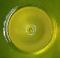
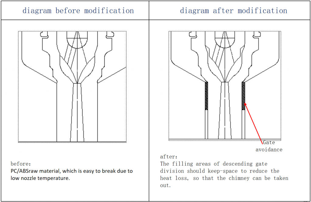
(6)Causes and solutions of the open hot runner gate blush
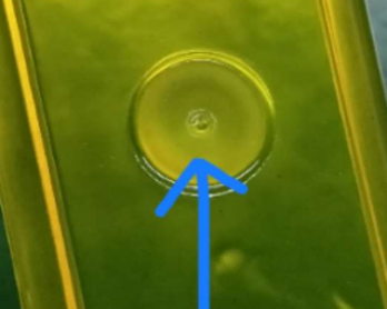
1.the temperature of the hot nozzle and the area around the gate is low, causing the break when opening mold.
improvement methods:increases the temperature of hot nozzles and mold. Decreases the cooling speed of the gate and extends the solidifying time of gate. Improving the blush.
2. The inlet is too big, so the holding pressure is too long, the gate is supersaturated, which causes the blush due to the external force.
improvement methods:smaller the gate, increase the holding pressure, and reduce the time of holding pressure.
3. Corrosion and TIP wear of the gate and hot nozzle. The edges of the gate is tooth shape, causing the gate blush.
improvement methods:Check if there is deformation in gate division and hot nozzle TIP and corrosion. Replace the strong material of the gate division according to the current situation.
(7) Causes and Countermeasures of common problems in hot runner injection molding
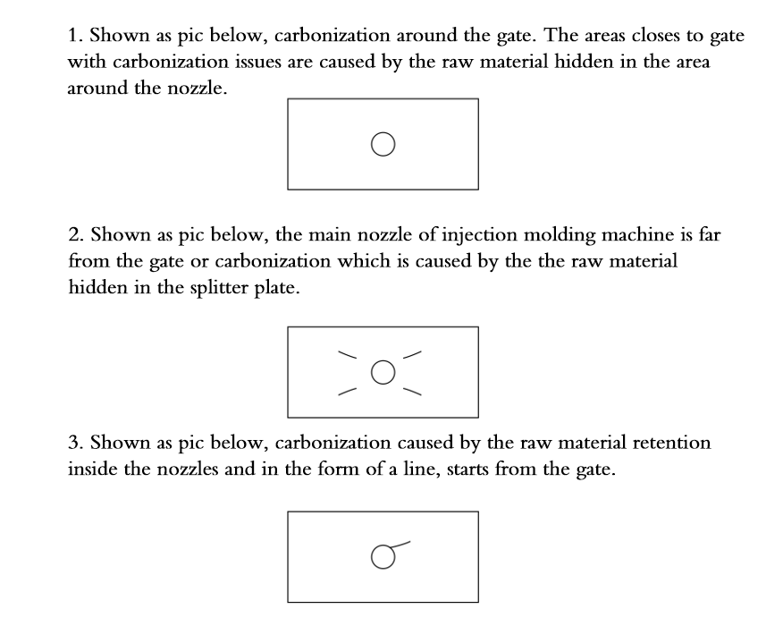
(8)Causes and solutions for the carbonization of hot runner system
(9) Causes and solutions for the leakage of the hot runner system
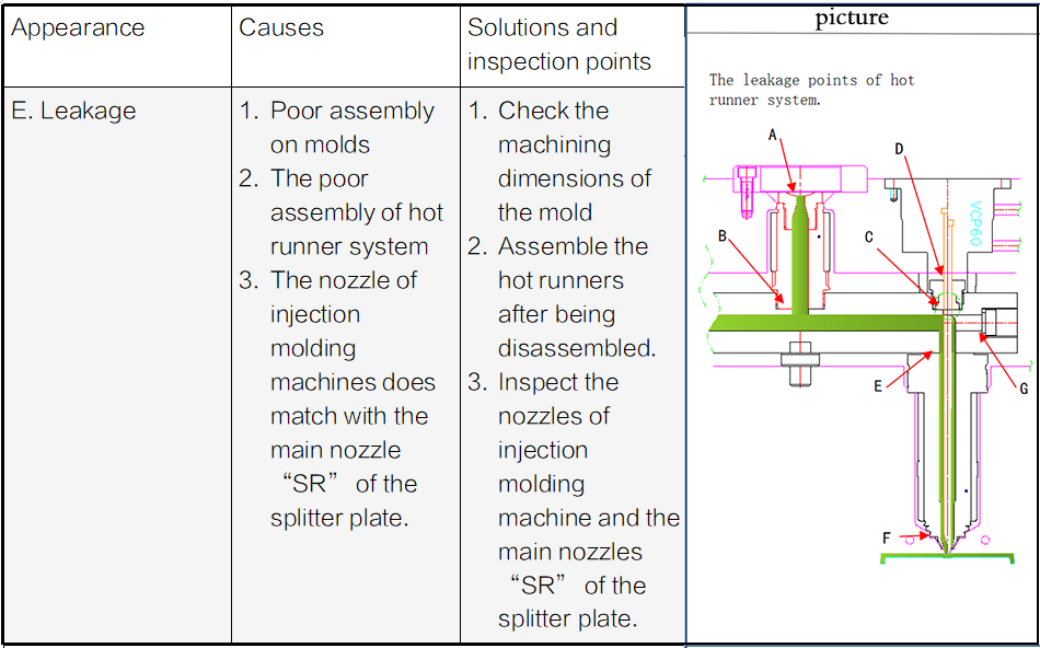
A part: the contact area of the injection machines and main nozzle doesn’t match due to the “SR”. The SR for the nozzles of injection molding machines is 1mm smaller than that of the main nozzle (SR21).
B part: the copper ring used to avoid leakage of the splitter plate and the main nozzle cannot be used for a second time. To avoid the leakage, M8 screws must be assembled evenly.
C part: the valve needle cover surface and the splitter plate surface are not complete. The needle valve cover does not close properly, causing leakage. Check the finish and cleanliness, and whether the needle valve is locked properly.
D part: there is leakage from the space between the valve needle and valve needle guide sleeve. If there is leakage, replaces the valve needle and the valve needle guide sleeve (not available in the open system).
E part: the copper ring used for prevent the leakage from the splitter and hot nozzles cannot be used again. The main reason for leakage results from the code template does not compress the hot nozzles sufficiently, which must be achieved by assure the dimension of the bearing plate.
F part: the poor coordination between the mold and the end of the hot nozzles. The incorrect value of depth and diameter are common mistakes. It needs to completely check the system assembly and molds.
G part: for switching the direction of the gate of the splitter plate, plug leakage areas with the plug or plug screws. Poor coordination between the plugs and splitter plate will lead to leakage, too.
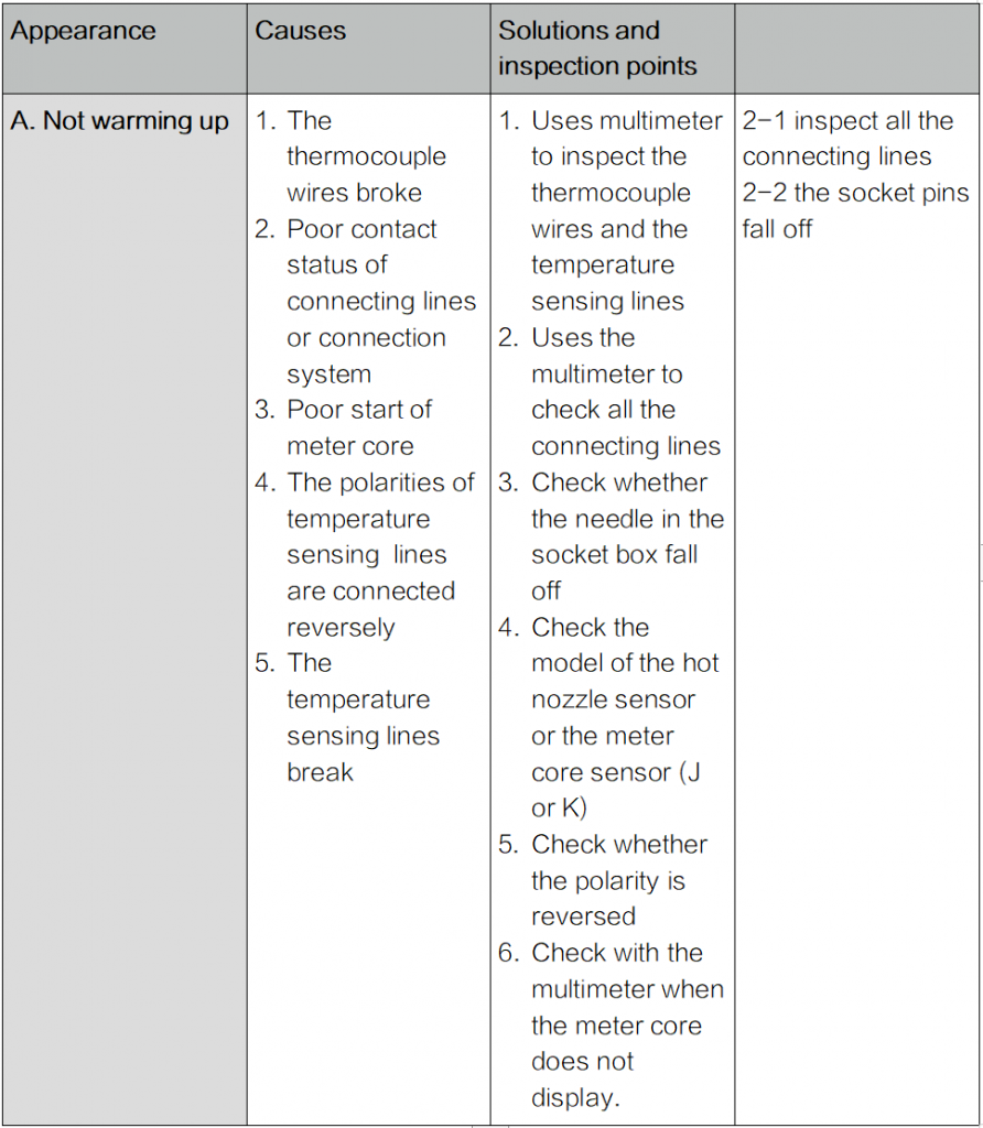
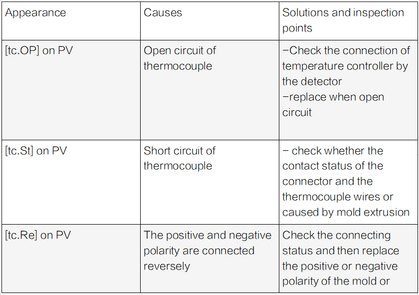
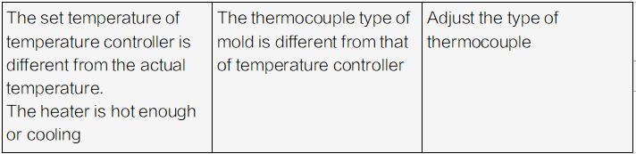
(10). Causes and solutions for the temperature control display of hot runner systems

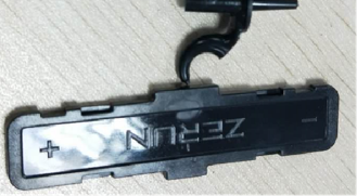
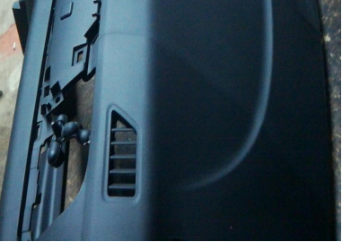
(11)successful cases of hot runner products
(12)Maintenance of hot runners
Inspect before the start
- Check the connecting lines status of junction box and the type of temperature sensing lines.
2. Check whether the power lines is disconnected with the temperature sensing lines, and displayed orderly.
3. Check whether the cable of temperature control box match the box
4. Check the junction box and cables
5. Check the resistacen and insulation status of the heating lines, and whether the temperature sensing lines is connected properly.
6. Installs the mold onto the injection molding machine and connects the cables.
7. inspect whether the switch of the power and meter core are closed
8. like input voltage(240V/380V)meet the standards of the temperatuer control box, connect the power line 9)double check the earth lines of the temperature control box (if cannot identify the earth line—green),so it is easy to burn the insurance lines and the thyristor.
9. check the installation of all the cooling water and hydraulic pipes/gas pipes
10. Check whether the voltage of the signal lines are matchable for the valve needle system
11. Check all the properties of injection molding machine.
shut-down procedures
1. uses the material which cleans the screw bars to empty the hot runner system.
2. Decreases the temperature of the temperature controller to the room temperature (25 degrees)
3. Shut down the temperature controller
4. Keep cooling water flowing in the molds till the temperature shows the room temperature.
start-up sequence
1. initiate the cooling water
2. Warm up the splitter plate and then warm up the nozzles.
3. Let the hot runner flow system stay for about 15 minutes when the set temperature is higher than about 20 ℃;
4. Practiecs three-time injection molding (short injection, repaid injection), check the flow the flow direction balance of the raw material.
5. Injection molding under normal temperature and inspect the samples (if the inspection time is too long, decreases the temperature of the temperature control box to avoid the carbonization.
6. formal injection molding
pause the programs
Pause: if pause, decreases the temperature of hot runners by 30%.
Operation mode of the temperature control box
Automation mode:Under the normal operation mode, the temperature is controllable. The temperature can be the same as the set temperature. Display switch: press the MODE button, the switch order of the temperature is as below: Set temperature=>output%=>ampere=>set temperature
standby mode:In a specific time range, lower the power to a required value. If stop production, press SEL for 1 sec by automation mode to switch into the standby mode. After that, change the set temperature value into the %ratio.
Maintenance
1. If the plastic has high heat sensitivity or corrosion, cleans the residual by PP at each stop.
2. Removes all the moisture, fog, grease and other items to prevent molds from rusting.
3. Places the molds at the dry and ventilate areas.
4. If the storage time is too long, the moisture might penetrate into the heater. So, dehumidify before using.
5. The valve runner system needs 1-2 times maintenance to prevent the carbonization, or the un-smooth movement of valve needle due to the uncleaned air.
(13)Dos and Don’ts before injection molding
1. Check whether the raw material is completely dry.
2. Clean up the barrel screw bar (change color)
3. Commissioning of low-voltage protection of switching mode machine, the length of the ejector pin. Clamping force.
4. Check and clean the grease in the exhaust grooves of mold cavity and PL surface. Confirm the lubrication degree of die guide post and guide sleeve.
5. Check the water circuits and if the actual mold temperature is qualified.
6. Check the connecting lines of hot runners and temperature control box. The snap on the junction box fastens the socket to prevent the snap from falling off during the injection.
7. Check the temperature of the meter core of temperature control box works properly.
8. After the temperature of hot runners is set, check whether the valve pressure/oil pressure is within the range. Pressure 6-10KG, oil pressure 30-50KG.
9. Inspect whether the valve needle moves smoothly.
10. White and transparent material:check if the barrel is cleaned and then clean the residual in the hot runner system.
(14)Dos and Don’ts after injection molding
1. After finish the injection molding, fibrous fireproof and easily decomposable raw materials need similar material like PC or PS PMMA ABS PP to heat the hot runners.
2. Switches off the meter core switch of temperature control box of hot runners one by one. finally, switch off the main switch.
3. Shut down the related devices, mold temperature machine, cooling water.
4. Applies anti-rust oil on molds.
5. One should be aware that no water gets into the junction box or connecting lines when un-mounting the water pipes. This prevents the heating temperature sensing accessories from being broken due to the short circuit.
6. Removes the connecting lines of the hot runners and then closes the junction box tightly to protect the socket in box.
Hot runner injection molds are essential parts for high-precision molds and plastic products, mainly for mass production with high profit. GREFEE not only manufactures complex hot runners export molds but also provides mold maintenance, repairing, and technical support.
If your injection molding project is in large numbers with high requirements, contact GREFEE for a custom plan.

Try GREFEE now,for free
We keep your uploaded files confidential and secure.