Designing Elements and Process Flow of Die Casting Die

Posted on : : Nov 12 , 2022 By GREFEE

Die casting mold is the important process tool in die casting production. The metal fluid is cooled and cursed in the die casting mod and finally comes into the die casting parts. The shapes, sizes, quality and smoothness of die casting production of parts are all related to the die casting mold. Thus, the design of die Casting mold is essential.
1、 Basic structure of die casting die
The commonly used die casting mold is consisted of two half mold, which are called fixed and movable mold. There are more complicated die casting molds, not only two half molds.

functions of die casting die components:
(1)The sprue connects to the pressure chamber or to the runner, including the sprue sleeve and splitter cone, etc.
(2)pouring system: channels that the liquid alloy enters into the cavity, including internal sprue, cross sprue, sprue, etc.
(3) mold cavity formed on the inserts and become the geometry of die casting parts.
(4) core pulling the movable core did the pulling and insertion action, including slideway, sliding block, oil cylinder, slash, etc.
(5) Exhaust gas from the overflow system and storage of cold metal residues.
(6) temperature control system controls the temperature of die casting mold, including cooling of the water pipes and heating oil pipes.
(7) ejection mechanics ejects the die casting parts out of the mod cavity, including the ejector bar, etc.
(8)Dynamic mold frame connection and fixed dynamic mold components, including sleeve plate, support plate, etc.
2. Design of die casting mold
Dos and Donts of die casting mold designing
the simple the structure, the better. The stable the movement, the better. To be preparaed for the daily maintenance and repairing in the future.
(2) the adjustment of injection molding system. Necessary modification is required during the adjustment.
(3) correctly selects all kinds of tolerance, scale and machining allowance ensure reliable mold fitting and required die casting accuracy.
Selects proper mold material and reliable thermal treatment process to ensure the service life of molds.
The mold should have sufficient rigidity and strength to bear the mold clamping force and expansion force so that there is no deformation during the production.
Using standardized die casting mold components to improve the economy and interchangeability.
In mold designing, the total projected area and injection specific pressure during die casting production shall also be calculated according to the projected area of the casting to select appropriate die casting machines. Formula:
F expansion force=100 P injection specific pressure × S projected area
F clamping force=F expansion force/K coefficient in most cases, K=0.85.
With correct die casting machine, designing the size of the die, the center position, the position of the reset pull rod hole, and the size of the parts connected with the die-casting machine according to the eccentric position of pressure injection and the moving and stationary plates of die casting machines.
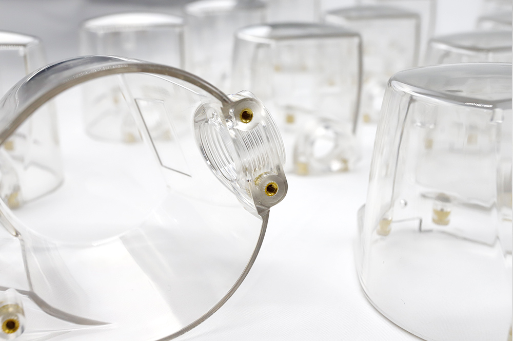
With the development of the automotive manufacturing industry, more and more components adopt aluminum alloy, such as the cylinder block, cylinder head, oil pan and various connecting brackets of automobile engine, etc. As the development of the die casting technology, all automotive manufacturers have higher requirements in the interior quality, especially the Volkswagen. The engine die-casting products of each model will require a corresponding technical requirements, as well as the porosity, which is a necessary requirement for each component.
Some components have extreme complex parts, requiring some corresponding structures on the mold to achieve the large volume production, such as the threaded holes with multiple angles on components. At the corresponding areas, the cores must be made so that the quality can be ensured.
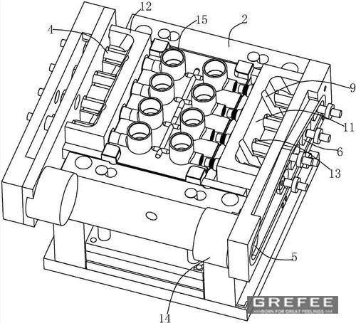
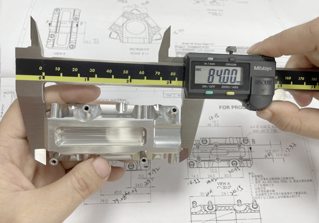
A is the locating hole, B is 3 M8 threaded holes with an angle of 10 degrees to the locating hole, of which the two threaded holes on the right are thorough holes. C are two bolt passes through the hole at an angle of 5 ° with the positioning hole; Hole D is a threaded hole 34 ° from the positioning hole, with a length of 38mm.
The core pulling structure can be divided into two types according to the driving mode, which are mechanical type and hydraulic type. The mechanical core pulling manly works by the bevel pin, bent pin, gear, rack during mold opening and closing processes to achieve the core pulling and resetting. The hydraulic core pulling working principles are simple, which utilizes the hydraulic cylinder to do the core pulling and resetting. The size of hydraulic cylinders can be selected according to the size of core pulling force and length of core pulling distance. The product in Fig.2, the first thing to consider that is the C and D three holes require to be casted in mold designing. This can be achieved by utilizing the hydraulic core pulling mechanism that adopts an angled slide way to realize the hole forming in production. In the Fig. 3, it demonstrates the schematic diagram of slideway mechanism of hole D. With this method, the hydraulic cylinder can be designed outside the molds, which can make the mold thinner and is convenient for the protection in the continual production.
During the continual production, the core pulling mechanism of mold may cause the deformation of core pulling holes due to multiple pulling, inserting and sliding. In the middle and late life of the mold, the core pulling and grinding will often occur. This can be fixed by adding an insert at the core pulling hole. If the core pulling holes are deformed, replacing the inserts (see Fig.4). This can also be applied to the ejector bar as long as the inserts can be added.
Due to the requirements of some drawings of some parts, some areas on the inserts require special shaped ejector rod of specified size. The four ejector rod forming parts in the circle (see Fig. 5) are in stepped form with a diameter of 8mm. Due to the mold cavity of castings is deep, so the gripping force is large and the force that required when ejecting is large. The ejector bar is likely to break during the die casting process because the diameter of it in the forming area of castings will be decided by the drawing of products. Besides, according to the features of products, the step thick and thin ejector pin is designed to ensure the life of the ejector pin.
Due to the requirements of some drawings of some parts, some areas on the inserts require special shaped ejector rod of specified size. The four ejector rod forming parts in the circle (see Fig. 5) are in stepped form with a diameter of 8mm. Due to the mold cavity of castings is deep, so the gripping force is large and the force that required when ejecting is large. The ejector bar is likely to break during the die casting process because the diameter of it in the forming area of castings will be decided by the drawing of products. Besides, according to the features of products, the step thick and thin ejector pin is designed to ensure the life of the ejector pin.
Since there are oil clyinders with two angles C and D on the mold, the three M8 threaded holes in B do not have extra space for precast holes with adopting oil cylinder mod. Two M8 threaded holes is 18mm deep. However, to ensure a good interior quality, the precast holes are required, so we fixed it with the method for butt joint of special-shaped core.
The cores are not properly joint but with a certain distance. the part where the two cores are butted is the normal mold exit angle (generally designed between 1 ° and 1.5 °). The mold exit angle on the outside of the two cores is the normal mold exit angle plus the angle with the positioning hole.
Sine at some thicker areas of some complex products, the interior quality canon be guaranteed through the coefficients of die casting. Thus, the inner squeezing structure should be considered in mold designing, which works by inserting the cores in the shortest period of time after the ejection completed to make this area compacted with no porosity. The forming area of squeezing and core pulling structure is without mold inclination, so it is only suitable for short distance structures.
3. Design of Die Casting Process System
After a broad outline of the mold designing is obtained, it moves on to the pouring system. In the past, we did this part based on practical experience by looking at two-dimensional or three-dimensional drawings. During the production, the interior quality can be adjusted by adjusting the position and direction. In the recent ten years, with the continual development of the numerical simulation technology of mold filling and solidification process in casting and marketing needs of the die casting industry, the simulation commercialization software during die casting process continual comes out. Many OEMs also require to see the die-casting simulation process before designing the mold and thus many mold manufacturers all use two simulation softwares, MAGMAsoft or ANYCASTING. At the beginning of designing, import the designed 3D into this program into this program, then set the coefficient for die casting. After a certain operation with simulation software,
a simulation animation close to actual production effect can be obtained.
The simulation results of die-casting process requirements are as follows:
(1). the liquid alloy reaches the inner runners more or less
(2). The liquid alloy should be filled stably
(3). No gas trapping or tuburlance in the filling process
(4). The liquid alloy should not block the slag collector passage before completing the
(5). All the cold metals should not be stored in the casting during the filling, but be kept in the slag collecting bags.
According to the filling simulation and particle tracking simulation, as well as the requirements of die casting process, the locations and sizes of runners of molds and slag collection bags should be optimized. The position of cooling water, heating oil pipe and point cooling in the mold can be determined according to the solidification simulation and wall thickness of castings. According to the mold erosion simulation, areas in the mold that need to be sprayed can be determined. Through the simulation analysis, the modification of the gate and slag collection bags can also be completed, which saves the die modification process caused by the deviation generated by experience during die manufacturing.
To further improve the quality of castings, some manufacturers utilize the vacuum tchnology to lower the scrapping rate for higher profit. Vacuum technology is quite mature in Japan and we also learned some from their experience. It requires that the area of the die exhaust duct is 1:100 of the punch area. Start the vacuum pump 0.4s before the start of rapid injection, and the mold designing can be determined according to the complexity and size of molds to ensure the number of the Vacuum exhaust wave plate or vacuum valve. The Fig.11 shows the vacuum pumping structure.
Vacuum technology lowers the scrpping rate to 20% or lower than the original scrapping rate. However, due to the price of equipments, some die casting manufacturers only apply it with the molds with higher scraping rate.
Die casting mold structure
The basic structure of die casting mold includes molding insert, mold base, guide piece, core pulling mechanism, pushing mechanism, heat balance system, etc. The Fig shows the mold on the die casting machine.
Flow Chart of Die Casting Mold Design and Development
Mold designing and developing flow chart demonstrates the work needs to be done in the designing stage as well as the overall idea of mold design, among which there are some possible defects of design and development processes related to standard certification on the design stage.
Key Points of Die Casting Mold Design
Using rapid prototyping technology and 3D software to establish proper castings, which preliminary determination of parting surface, gating system position and mold heat balance system. Convert 2D casting drawing to 3D solid data as required. According to the complexity and wall thickness of the casting, determine the reasonable shrinkage rate, generally adjust and determine the position and shape of the parting surface. Selecting the position and diameter of the injection punch and the number of pieces according to the data of the die casting machine. Then, the pouring system and overflow system should be provided with three-dimensional modeling drawings.
Carrying out the simulation of flow field and temperature field to further optimize the mold pouring system and mold thermal balance system. After processing the data of casting, gating system and overflow system, importing the process coefficient, physic coefficients of die casting alloys and other boundary condition data. With the simulation softwares, the flow direction of filling process of alloy and liquid alloy can be simulated. It also can carry out the solidification and temperature simulation drawing to further optimize the pouring system and determine the cooling points of molds. The outcome of simulation, pictures and images can present the flow direction of liquid alloys and the distribution of casting temperature during the whole filling process. Through analysation, the defects can be found. In the following designing process, the locations, flow direction, and cross section area of inner gates can be optimized to improve the filling effect and reduces the possibility of defects.
Starting the overall mold structure designing and simulation process according to the models. In the meantime, we can also carry out the general layout of mold, which includes the following aspects. According to the data of die casting machines, the general layout of mold determines the injection position and punch diameter. Besides, the injection position should make sure that the casting is at the centre of the die casting machine plate, and the four pull rods of the die-casting machine shall not interfere with the core pulling mechanism. The injection position is related to whether the casting can eject the punch head successfully. The diameter of the punch head directly affects the size of injection specific pressure, and further affects the mold clamping force required of die casting mold.
Therefore, these two parameters are the first step of our design.
Factors that need to consider when designing the formed insert and cores include the strength and rigidity of the forming insert, the ruler of the sealing surface, the splicing between inserts, the arrangement of the push rod and the cooling point. Properly arranging these points is the basis of the long service life. For large scale molds, matching mode of patching and sealing surface of vulnerable parts is especially important not only in preventing the early damages of mold in the early stages and the loss of aluminum in the die casting process, but also necessary for the ventilation of large scale molds and processing of molds.
Set the mold base on the core pulling mechanism
For small and medium-sized die casting molds, standard mold bases can be directly selected from. For large dies, the rigidity and strength of the die base must be calculated to prevent the elastic deformation of the Chinese mold base during die casting affecting the dimensional accuracy of the die casting.
important factors of the core designing include the fit between running position, pressing block and wear-resistant block, accurate location, the principle of friction after high temperature expansion during production, as well as the evaluation of fit clearance after high temperature expansion.
The square key is used for positioning between the forming slider and the slider seat, and the lubricates of the core pulling is also the key of this design, which directly affect the reliability of continuous operation of die-casting mold. Great lubricate system is also essential for increasing the efficiency of die casting production.
Mold inserts & Heat
How to dissipate the heat must be considered in mold designing, especially for the large scale molds. The thermal balance system of die casting mold directly affects the size and interior quality of castings.
Rapid installation and accurate flow control are the development trend of modern mold heat balance system. With the development of modern industry, the selection of the heat balance components more tends to the mode of designing, which is that component manufacturers provide 2D and 3D data of components to the designers to select and use. This not only ensures the quality of components but also shortens the designing cycle.
The ejecting mechanisms designed by the famous suppliers in the mold components industry include two forms.
Mechanical ejecting and hydraulic ejecting. The mechanical ejecting utilizes the automatic ejecting mechanism to eject. While, hydraulic mechanism relies on the oil cylinder on the mold to eject. The key of ejecting mechanism is to try to make the center of the pushing force concentric with the center of the de-molding force, which requires the ejecting mechanism has great ejecting guidance, rigidity and reliable working stability.
For large scale molds, ejecting mechanism is heavy and the components of it is like to stuck with the frameworks due to inclination of pushing bar. In the meantime, due to the thermal effect, the ejecting mechanism of mold is also largely affected. Thus, positioning between push out element and mold frame and fixing position of push plate guide post are extremely important. The push plate guide post generally is fixed on the template. Using the round pin or square key with larger diameter to locate the formwork, sizing block and formwork frame on the template so that it can maximumly eliminate the influence of thermal inflation or adopting rolling bearing and guide plate to support the ejection element if it is necessary.
Another one need to pay attention to is the hole slip between elements in designing. Mold designers in North America normally add a special grease plate of the hole sliding push rod strengthens the hole sliding of the push element on the back of the mold framework, or adding the lubricating oil plate at the bottom of the movable mold frame. There is an oil passage connecting with the push rod through hole. When working, the lubricating oil mechanism is added to prevent jamming.
In the whole mold structure, guiding and positioning mechanism are the most important factors to the operation of mold, which also directly affect the size of castings: The guiding mechanism of mold mainly includes mold closing guide, core pulling guide, and the fitting surface of the guide mechanism and accessories require the use of friction agents made of special materials. The lubricating oil circuit is necessary. The guiding mechanism of extreme large slides adopts copper sleeves and guide form of hard guide post. With good positioning, the slide can move stably and accurately. Push plate guide post is quenched with material. Push plate guide sleeve is made of beryllium bronze with good wearing resistance.
The push plate guide is fixed on the template with little thermal impacts, so the positioning is more accurate. The whole mols positioning mechanism includes the positioning between the dynamic and static molds, the positioning between the ejection reset, the positioning between the forming slider and the slider seat, the positioning between the ejection part of the mold base and the mold frame, etc. The positioning between movable and fixed molds is a kind of movable positioning, which requires higher accuracy and smaller molds. The concave and convex surfaces between formed inserts can be used to fix the large scale die casting mold and the special positioning mechanism can eliminate the impact of thermal inflation to the mold position accuracy. Another kind of positioning mechanism is the positioning between components, which is to fix the positioning unit with with round pin and square key. The Positioning of convex and concave surfaces between formed inserts can prevent the staggered edges by ensuring that accuracy of positioning between fixed and movable mold.
In addition to the above mechanisms, including vacuum, extrusion, exhaust mechanism, and others, some molds also have special requirements for vacuum system, extrusion mechanism, wave plate exhaust, etc. The design of vacuum system mainly refers to the design of sealing form to keep good sealing between the formed parts of the mold under normal mold working temperature. General, it seals with the silicone and rubber. The key elements of the squeezing system are the control of extrusion time and amount to ensure the extrusion effect. Wave plate exhaust is a centralized exhaust method that is commonly used in many cases, especially for the aluminum alloy castings with thin wall thickness, connectors with high compactness requirements and magnesium alloy die casting. Normally, the parts are large but it also should make sure that no liquid alloy splashes during die casting.
MORE BOLG
Insert mold in injection mold service
What are advantages and disadvantages of Zinc alloy and Aluminum alloy?
Inspection standards for injection molded partappearance
How to judge the quality of your plastic products?
Inspection standards for CNC machining
To ensure that your products are 100% qualified
Categories

Try GREFEE now,for free
We keep your uploaded files confidential and secure.