How the position of gate affects the quality of injection molding products ?

Posted on : Nov 16 , 2022 By GREFEE
Gates are essentials to the injection molding system and the types and sizes directly affect the quality of products and the costs. There are a wide variety of gates and the sizes of them are slightly different. Meanwhile, its characteristics and application status are different, too.
The quality of parts are related to the shapes, sizes and feeding positions. There are many qaulity defects are caused by the improper design of gates, like shrinkage cavity, material shortage, white spot, weld line, brittleness, decomposition and warpage. Thus, a proper design is the key to ensure the good quality.
The design of gates decides the properties of plastic, shapes of plastic, size of cross section, mold structures, and injection coefficients, etc. The main requirement makes the melt to enter into the mold cavity with a fast speed and it can be timely cooled and closed after being filled. Therefore, the cross section area should be small and the length should be short so that the flow speed will increase and it can be quickly cooled and closed, which’s convenient to separate the plastic parts and gate aggregates without obvious marks of gates and ensures the appearance of parts.
Influence of gate position on the quality of injection molded products
Gate position & shrinkage cavity
When the wall thickness difference is large, to reduce the flow resistance with avoiding the preconditions for injection and ensure the effective transmission of plastic pressure to the thick area of wall to reduce the shrinkages, the gates should be at the thickest area of cross section area, which is beneficial to the feeding, like the reinforced ribs of parts can be used as the flow paths to improve the flow conditions.
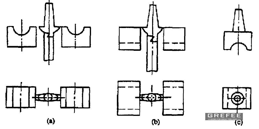
As shown in the figure below,
(a) the plastic part will appear dents due to severe shrinkage.
(b) the gate is at the thick wall of the plastic part to overcome the dent defect.
(c) the use of direct gate greatly improves the filling conditions and the quality of plastic parts, but leaves a large mark of gate removal.
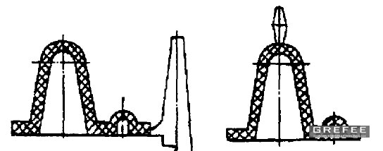
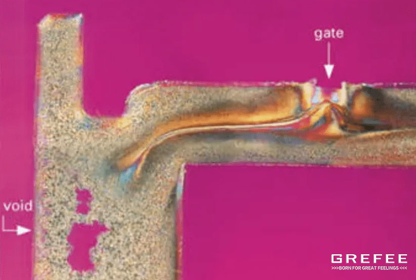
Position of gate & ventilation
Ventilation is associated with the position of gates, which is usually far away from the ventilate area, or the plastic melt may enter into the closed ventilate system earlier and causes the air in the cavity cannot be voided smoothly. As shown that the location of the gate in the left figure, during mold filling, the melt will quickly close the exhaust gap at the parting surface of the mold, resulting in the gas cannot get out of the cavity completely and causes a large filling resistance and other defects, like bubbles, burning, etc. If changes it into the way shown in the right figure, the defects could be overcome and the exhaust efficient will be improved.
Location of gate & welding marks
The location of gates not only determines the flow direction of polymers and flow balance, but also affects the shapes of the front of the solution flow and effect of pressure holding. The shapes of the front of the solution flow will lead to the welding marks directly and affects the appearance.
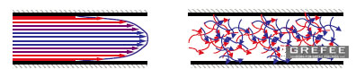
Location of gates & shrinkage
The location of gates is also associated with the deformation of parts and shrinkages. For the crystalline plastics, there is a big difference between the shrinkage rate towards the flow direction of plastic and the shrinkage of flow direction vertically. With using different types of gates, the deformation degree is different, too. Indeed, the location of gates are more important than the number of gates.
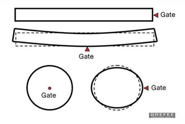
The location of gates will affect the orientation of polymer molecular and shrinkage of parts. The figure above shows that if a long and thin product requires a straightness, gates are required at the end of the product, which is also true for for circular products that requires the gates to be in the center of the circle rather than on the side.
Location of gate & plastic appearance
Gate marks are unavoidable so the location of gates should not affect the appearance of plastic parts, like the edge, bottom and inside of the plastic parts. This is especially for the plastic parts with high requirements for appearance quality.
Location of gate & plastic flow
When deciding the location of gates, the maximum flow distance ratio allowed for plastics, referred to as flow ratio to ensure that the melt could fill out the cavity. The maximum flow distance ration refers to the ratio of the maximum length of the melt flowing in the cavity to the thickness of the runner. The allowable value of flow ratio varies according to the difference of the melt property, temperature, injection pressure, etc. If the calculated flow ratio is greater than the allowable value, then the thickness of products should be increased or the location of gates should be changed, or adopting the multi-gate mode to reduce the flow ratio.
Basic design principles of gate
(1) gates should be at the thick wall of formed products so that the plastic can flow from the thick wall to thin wall area to reduce the loss of pressure. The melt of plastic should be ejected into the cavity quickly with the minimum thermal and pressure loss and in the shortest route.
(2) gates should be at the places where the products are most easily removed, and try not to affect the appearance (such as flow marks).
(3) Gates should make the plastic flow evenly along the parallel direction of the cavity and helps with the ventilation.
(4) gates should be at the areas that prevent the welding marks and flow marks from generated at the important sites of products to reduce the strength of products.
(5) when it comes to one mold multi-cav, the size and location of gates should depend on the distance between gate and sprue and size of products.
(6) the location of gates should avoid to impact the weak cores, inserts, rows directly to in case the deformation.
(7) the location of gates should depends on the shrinkage of products in different horizontal and vertical directions. The temperature and pressure when the melt enters into the gate are same to ensure that the shrinkage ratio in each cavity is same.
(8) The turning point of the splitter channel should be transited by an arc, and the connection with the gate should be processed into a bevel to facilitate the flow of the melt.
MORE BOLG
Insert mold in injection mold service
What are advantages and disadvantages of Zinc alloy and Aluminum alloy?
Inspection standards for injection molded partappearance
How to judge the quality of your plastic products?
Inspection standards for CNC machining
To ensure that your products are 100% qualified
Categories

Try GREFEE now,for free
We keep your uploaded files confidential and secure.