Except for ISO9001, GREFEE has more standards for mold machining

Posted on : April 15, 2022 By GREFEE
Except for ISO9001, GREFEE has more standards for mold machining
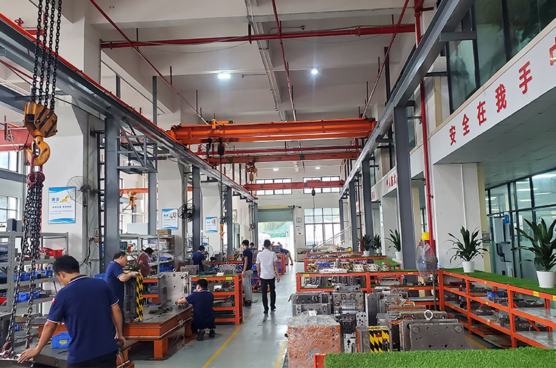
In GREFEE, all production must strictly follow the ISO 9001 quality control system. However, we have more than that. With more than 20 years of experience, we developed a more rigorous production standard for the details in production, which improves our production rates significantly. Besides, its convenient operation reduces the occurrence of mistakes.CONTACT US
1. Mold base
- The customer mold number should be printed on the non-base level side, and the fonts must be clear, tidy, and correct.
- Labeled the customer numbers on the square iron according to the requirements.
- The four corners between the A and B plate should set ppy slot, big model:40X45degree; depth 10 mm (two sides calculation), small model 25X45 degree; depth 6mm (two sides calculation).
- Clamp slot:height (25-35)X depth(20-30)。
- Ejector holes:diameter (35-40)generally is one. The big model needs more (except when customers required)
- The appearance of the mold base has to be clean, flat, with no rust, no extra holes or evident scratches, sinks, etc. Do not mess with the mold base by grinding machines or files.
- Parting surface, pin point gate moving plate, and stripper plate clamped by the lock template. The lock template should be installed on the die casting mold at the side of the operators or the top. On the same plate, it needs one more screw hole, and this hole will position the clamping plate with the screws of the original clamping plate together in case the accidents in production.
- Corners of non-sealing positioning need undercuts, which have to be mechanical undercuts. Forbids to undercut by grinding machine or files.
- Mold surface, internal model, slides, wedges, briquette, and other items must be symmetrical if typing code is needed. Besides, add a 0.5 mm depth circular concave at the code position. Using the standard codes typing at the central area.
2. Screw
- All of the countersunk heads of the screw holes must be made into a flat base with undercuts. All of the screw teeth must be cooperate effectively to make the length of the screw teeth exceed that of the diameter, and the teeth holes must be vertical. The screw heads should be 1-2mm under the plate.
- The pull rod screw must be tighten.
- The central distance of the internal model screw is a multiple of 20 and is easy for the CNC machining.
3. Sprue bushing
- The sprue bushing is the standard type of sprue bushing. It must be positioned to prevent rotation and pressed The sprue bushing is the standard type of sprue bushing. It must be positioned to prevent rotation and pressed to avoid falling off and loss due to some reasons.
- The pin point gate sprue bushing and special sprue bushing should be manufactured according to the sheet.
- The outlet mold sprue bushing and hot nozzle should be processed according to the drawing sheet.
4. Mounting holes
- The centre distance of the mounting screws (is centered by the sprue bushing) a、diameter1/2X7” two tooth holes b、diameter 5/8X10” two tooth holes c、diameter 5/8X14” two tooth holes d、follow the customer’s requirements:(notified by drawing sheet)
- The thread length of the mounting holes should not be less than 1.5 times that screw diameter and should be vertical.CONTACT US

5. Support pillar
- Two sides must grinded to be flat and parallel without sinks and 0.05-0.2 higher than the square iron (depends on the size and the condition of the molds)
- Deciding the number, size, and height according to the size of die casting mold and specific circumstances.
- The air holes of the ejector pin plate are 2-3mm higher than the support pillar, are fixed on the bottom plate by screws, and are located in the centre of the air holes of the ejector pin plate.
6. Stop pin
- The stop pin should be a standard type no matter the size of the mold. The stop pins on one mold must be of the same height.
- The stop pins are on the bottom plate. Drilling through the base plate for the mating holes and one each following the return pin bottom. For the remaining holes, add one more mating hole every 100-150 according to the size of the mold.
7. Spring
- The ordinary die casting molds utilize the blue spring. The export mold and the mold with a forced return system should utilize the yellow spring – DAIDO Spring
- The spring has a preload of 8-15mm according to the size and circumstances. The length of the spring must not be less than 60% of its original length.
- The calculation of the spring length: preload + stroke/preload + hole depth =0.3-0.4. total length = preload + stroke + hole depth
- For too-long spring and export mold, it must add return pins inside the internal holes of the spring and be fixed at the bottom plates and support plates.
8. Thimble
- The internal mold ejector pin holes should have at least a 20 mm positive sealing compound. The remaining part can keep 0.5-1mm space, including the mold base and ejector pin plate. The largest keep-space diameter of the ejector pin whose diameter is below 1.5, is 1/64.
- The ejector pins higher than 1.5mm should be drilled by the joran and then reset by the reamer.
- The ejector pins can be rotated manually after installation but cannot move forward or backward. It has to be smooth but not loosen when pushing or pulling.
- The bottom of the ejector pin’s head is parallel with the ejector plate or lower than the ejector pin plate (within 0.05). The countersunk heads of ejector pins need to be paralleled with the bottom diameter and keep 0.5-1mm space.
- The ejector pins of the R surface or side surface and the ejector pins of the forming cavity need to be positioned by the dowel pin. If without specific situations, it does not suggest other positioning methods. The end face and the mold surface should be polished together. All ejector pins must be labeled with the number on the back.
- The ejector pin marks on the end-use products can not be higher than the product surface or below the surface no more than 0.05mm.
- The slag well besides the PVC pin is usually between 6mm to 8 mm. The single side of the sharpened area is 5-10 degrees, and its large part forms stairs with the outer diameter of the ejector pins. There is no burr or undercut area. The ejector pin cavity needs to be polished smooth, and no slags are allowed. The ejector pin is usually 5/32 of the diameter. The specific situations are excluded.CONTACT US
9. ejector sleeve
- The ordinary ejector sleeve pillars have to install a draft angle of 0.5-1 degree and need to be polished.
- If there is a lack of ejector sleeve pins, tighten the pillars with two grub screws. Pressing the ejector pins bit with a press plate if necessary.
- When the internal pin of the ejector sleeve K/O the cavity, the inside pins cannot be adjusted by the screws randomly after mold clamping. The ejector pin head must be pushed down to the bottom and then fit with the kiss-off part.
- The allowance of the ejector sleeve length and the cutting allowance should not exceed 3mm, so the ejector sleeve should be appropriately fit well.
- The ejector sleeve pin and the internal pin of the ejector sleeve must be concentric. The ejector sleeve holes and pin holes also should be concentric to avoid burning the ejector sleeve and breaking the internal pin.
10. slide, lifter
- The actions of the slide must be initiated by the angle pin or angle plate or slingshot, etc.
- The slide must be positioned tightly after the mold opening to a certain distance. Short stroke can use a slingshot, locate screws, or the oil cylinder slide.
- The slide is block-structured and must have a positioning designed at the block. After machining, the block needs heat treatment to make it hardened.
- The slide bottom and the wedge should be set with hard materials.
- There are net form oil pits or double gold wired oil pits on the sliding sides, like slide, straight ejector, and the lifter. The oil pits need to be neat. Oil pits on the straight ejector and the lifter should have a 5mm distance from the cavity side after reaching the ejection limit to prevent the oil from leaking into the cavity of the products.
- The straight ejector and the lifter need the ejector pin plate limit if necessary, and the limit must be positioned around the ejector holes rather than on the ejector pins.
- The slide action must be smooth but not loosen. Besides, the slide must be compressed when mold clamping.
- The slide uses an oil cylinder or air cylinder and should install the lead limit switch. It has to be on the base, which is at the side slide of the mold base, to prevent the electric wires broken.
- The straight ejector and the angle lifter need heat treatment or surface nitriding treatment.
11. Cooling
- The design of the cooling system must follow the drawing sheet. Issues need to discuss with the engineering department before adjusting.
- The tooth of cooling holes must follow the customer’s requirements by selecting the metric or the imperial units with the letters “IN” or “OUT” to distinguish different exits and entrances.
- Plug the cooling system with plugs. Will be notified if there are any changes.
- Before delivering the mold to customers, the water carrier system needs to test with 3 mins 25PSI water pressure without issues, then it is qualified to ship to the customers.
- The cooling water holes after machining must use an iron branch and air gun to remove the inside fillings and trash. The corner of the cooling system should connect properly to promise smooth water transportation.
- The rubber ring should be designed 0.5mm-0.7mm higher. When compressed, the rubber ring pits need space.
- The export molds manufactured by the own factory need flat base counterbores with 25.4*25 diameter at the entrances and exits of the cooling system.
- The fountain water delivery spray pipe has to be as long as possible because too short a spray pipe will lead to still water existing in the holes, which affects the cooling effect.
- The water separators should not separate the bottom area to prevent clogs.
- The area with too many rubber rings or dense places should add screws around to prevent internal mold deformation or water leakage.
12. Insert pins, moving pin positioning
- The sliding side has a direction that can rotate. After rotation, the inserts affect the size and appearance of the products should be positioned with dowel pins.
- The same moving pins and inserts must be marked if there is working position.
- The large insert need cooling water.
- If there are many replaceable inserts or insert pins, can fix them at the squire iron or other areas of the mold base. If the insert is large or the number of it is too much, prepare another wooden box with mold numbers and customer numbers for storing the inserts.CONTACT US
13. exhaust pit
- The exhaust slot side which connects the cavity is 0.005-002mm deep (depends on the sizing). The total length is 3-5mm, and the outer end is 0.5mm in depth, which passes through the outside of the mold.
- Exhaust grooves on the bottom of the guide pins are 0.5mm deep.
- The exterior, insert pins, the bottom of the inserts, deep holes, deep ribs, blind holes, and areas that are likely to have air-trapping must install an exhausted groove.
- The exhaust groove normally uses a grinding machine to grind or work with the help of a numerical controlling lathe. Forbid to use the grinding machine to exhaust. The exhaust groove should be placed organized.
- There should have exhaust grooves on the bottom of the flow channels.
14. Water entry channel
- The tap holes of the sprue bushing and the flow channels need to polish the machining marks.
- The end of each flow channel must have an exhaust system and cold slug well (length = 1.5X flow channel diameter)flow corner has to be R0.5mm distance left for the filling.
- The cross section of the flow channel can be circular or trapezoid (10 degrees – 15 degrees stripping)
- The tolerance for the circular flow channel clamping line dislocation should not exceed 0.1mm.
- The flow channel ejector pin is 5-8mm lower than that of the flow channel and works as the cold slag well.
- The gate area should be smooth, including the hidden thimble gate.
15. CNC, wire cutting, EDM
- The copper electrode should be measured correctly, polished, and smooth. Make sure the burrs and the cooper slag generated from the wire cutting have to be cleaned thoroughly, then it can be processed on the EDM machine. Contumely observing, measuring, and inspecting during the machining process. If there are problems, then they need to be dealt with in time or will be the operators’ responsibility.
- Copper electrode of wire cutting and holes must check, and the size and positions must be correct. If there are any issues during the production, they should stop immediately and be reported within the shift.
- The steel material and copper electrode of the CNC has to be inspected by the staff in each shift. Inspect whether the size is correct or not and the shape is clear and sharp or not. Areas that need clean up or post-treatment (if keep-space is needed) should be marked obviously and reported to the operators or the chargers of the follow-up. If there are issues, report immediately.
- Cooper electrode has to be double checked with the drawing sheet about the Cooper electrode number, direction, position size, depth, spark gap, collision number reference, and if the keep-space of the cooper electrode is enough.
- In the shift processing, it needs to make sure whether the parts need to move flatly or rotate. After the shifting, it needs to inspect whether the position is correct or not, then can leave.
16. Machining notice
- The mold base which has not been machined or already machined should be aware to prevent rust, scratching, and dented. The mold plate cannot drag on the ground.
- In machining the cavity, it should place the isopachous rugs and papers when the PL contact with the platform jaw or working tables of other lathes. Avoid dragging the mold on the working table to prevent scratches.
- Tightening all of the screws with moderate force. Be cautious of too much strength, causing the reverse screw, cup head sliding, broken screw, etc.
- Guide pin, ejector guide bush, and other mold accessories be labeled with numbers and well stored when opening the new mold base to prevent loss or mixing with other molds.
- Mold includes (internal mold and mold base) and should all be manufactured according to the drawing sheet.
- When fitting mold, forbid to knock the mold plate directly. Put some flat steel before knocking the plate.
- When clamping mold, the side lock should be perfectly matched, including the side lock of standard part mold cannot FIT angular surface but only adjust by deeply grinding or lightly grinding.
- When marking out, do not marking-out too deep so that it is hard to remove after completing the machining and affects the appearance.
- The die casting molds which need to be tested on that day do not need to spray the anti-rust oil or other washing oil.
17. Pre-reset mechanism (forced returning device)
- Except for the swing bar, the accessories of the pre-reset mechanism can be fixed by the screw and positioning device.
- The swing bar uses the shoulder screw be the rotating shaft. There is no space between the screw and the swing bars. Areas close to the cavity need to be positioned to prevent the swing bar from over-swing to the cavity side, causing it to be invalid.
- Molds with a pre-reset mechanism, the ejector pin plate should utilize the DAIDO spring (yellow spring) and the limit mechanism.
- All accessories should have heat treatment.
- The common action parts (swing bar part) should be as long as possible. The pinpoint gate structure normally should be fixed on the A plate.
- The pre-reset structure should be tested after manufactured. The method is to remove the slingshot of the ejector pin plate and reverse the mold. Now, the ejector pin plate is in the ejected state and is suitable for mold clamping. Inspect whether the ejector pin plate is stuck on the bottom. If not, which means that the forced return device is unqualified. When inspecting, un-mounting the internal mold of the cavity.
- The mold in production has specific requirements. There should have a warning board containing the notices on the evident areas.CONTACT US
18. Rubber plug, pull bar screw, pulling plate
- The rubber plug area should be 1-2 mm sink and then fixed by the screws. The rubber plug and the holes should be concentric. The hole should be the fillet (R = 1mm) to prevent the sharp corner from damaging the rubber plug.
- Drawbar screw holes have to be vertical. Hexagon socket un-countersunk head screws on one mold plate should be fully inserted with the same depth to prevent the screw broken and the parts from being scratched due to unequal force.
- Standard pinpoint gate tie bar screw only for pulling No.1 & No.2 plates. A plate is positioned by the metal ring shim on the cavity guide pins. The simplified pinpoint gate opens the No.1&No.2 plate by the drawbar screw and uses it to locate the A plate. The outer edge of the mold should install a pull plate to protect it. The possible friction areas between the pull plate and the moving plate should keep space for 0.5mm.
- When the pull plate is used for opening mold and positioning, the pull plate with the same function should work in the meantime to assure balance. To assure this, the pull plate set-screw will be set in one metal ring shim, and the end of the pull plate pits need one insert to adjust the balance. The inserts need heat treatment.
19. mold polished
- Mold polished is the last step of die casting mold manufacturing. Once there is a mistake, the mold will be scrapped. Zinc alloy die-casting factories have to make a new one, and it needs patience and technological improvements.
- When delivering the molds to the mold polished operating room, it needs to let the operators know the requirements and when the polishing can stop. Especially the shut-off and kiss-off areas, and parting lines, operators should emphasize these areas. Parts that have accessories need to attach accessories. Places that have requirements on size need to know well about how much allowance is needed to assure the size. Areas with parting lines that can be polished together.
- The placement of nails of building blocks needs to use the male gauge to measure the size while polishing. All the practices must follow the guides in case of accidents.
- No chatting that is unrelated to the work. The operators should be responsible for unqualified molds due to neglecting duty in the shift.
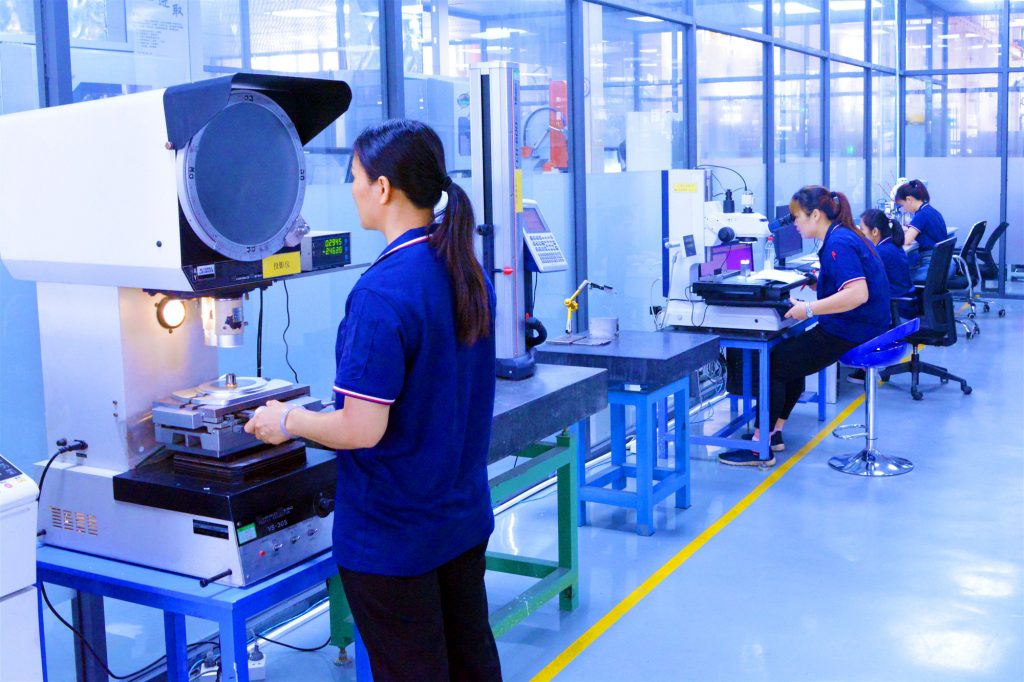
20. Mold inspection
- Before leaving the factory,molds have to go through several procedures before delivery. It requires the quality inspection staff to carefully check the qualification of each section and fill out the mold completion sheet with √” OK” or“-”. Without this item, the two symbols cannot be ticked together, resulting in ambiguity. No alterations are allowed on the sheet.
- The one who neglects the duty or does not follow the guides, causing production failures, will be responsible for the mistakes. Zinc alloy die-casting factor has to be strictly required by the staff in case of accidents on duty.
GREFEE has more than 20 years of experience in the mold industry and continues to perfect our skills on each step. All the operators in GREFEE have received comprehensive and professional training. We have grown from a start-up into a leading company in the industry. If you need help with your project, contact us, our staff will reach you soon.
MORE BOLG
Insert mold in injection mold service
What are advantages and disadvantages of Zinc alloy and Aluminum alloy?
Inspection standards for injection molded partappearance
How to judge the quality of your plastic products?
Inspection standards for CNC machining
To ensure that your products are 100% qualified
Categories

Try GREFEE now,for free
We keep your uploaded files confidential and secure.