Injection Mold Design of Automotive Headlights

Posted on : Nov 28 , 2022 By GREFEE
Injection Mold Design of Automotive Headlights
Injection mold design
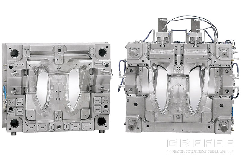
As the auto lamp mold is large scale mold and its parting surface is complex, many injection molding parts manufacturers in the world utilize the integrated structure in the injection molding products and molds, which means the fixed mold plate a of the mold is the fixed mold forming part, and the movable mold plate B of the mold is the movable mold forming part. The advantages of this kind of structure include a compact structure, good strength and rigidity, small mold volume, cumbersome processes reduction, such as opening the frame, matching the frame and manufacturing the wedge.
Below points have been accomplished in this kind of mold design
1.The parting surface is smooth without sharp corners, thin steel, ling or spot sealing. It adopts plane stealing method which uses the extension, sweeping, mesh and other methods when splitting the module. The parting surface is constructed according to the shape of the plastic part. The parting surface of the lamp mold requires a high condition, and the constructed surface should not made without wrinkles. Besides, the constructed parting surface can effectively ensure the CNC machining accuracy without EDM angle clearing. On top of that, the parting surface is not easy to run rough edges. The high-speed machine is used for the light knife of the parting surface of the auto lamp mold, and the spindle speed of the machine tool should be maintained to be at least 20000 rpm.
2. For the coordination part between the insert and the moving die, an appropriate process inverted R angle or clearance position is required at the root of the seam, which simplifies the processing procedure, reduces the processing time and improves the processing efficiency.
3. R angle should be designed at all non forming corners to prevent stress cracking. The R angle should not be less than R5. According to the size of the mold, a large R angle is required as far as possible. Sharp edges on the mold are quite likely result in accidents during the operations. The inverted C angle or R angle should be design on the edges on the mold that are not involved in forming or matching, and larger chamfer is also needed as far as possible according to the size of the mold.
4. Clearance of parting surface: the width of the mold parting surface is 40mm, and the fixed and moving molds outside the parting surface should allow clearance of 1mm to effectively reduce the processing time. The clearance on parting surface not only refers to the ones on the peripheral parting surface, but also includes a large area of parting surface. Special instruction: the width of the mold parting surface includes the venting grooves. A pressure bearing block is required at a large area of clearance to maintain a uniform stress in the mold and avoid long-term production of the mold. While the clearance is designed in the k/o area, a venting hole is required in the fixed mold or moving mold to help the release of the compressed air during mold closing of the fixed and moving mold.
5. the parting surface should be constructed according to the shape of the parts, and the parts ought to be optimized if necessary. For medium and large scale molds, opening the pressure plate groove as far as possible for the CNC processing. In designing the parting surface, simplifying the mold processing and try to make it smooth. The parting surface is produced without thin steel and sharp corners, and the s/o angle should be appropriate.
6. Smooth and flat parting surface. In the UG parting, multiple small broken surfaces (the cutter is easy to bounce during CNC processing, and the processing accuracy is reduced) is not allowed. The use of the extended surface, grid surface and sweeping surface is encouraged for the construction parting surface, or extend the sealing surface for 10-20mm first and then produce the stretching surface and transition surface. The design of the sealing surface should be based on the tonnage of the injection molding machine and mold size.
7. All the s/o angles on the parting surface or s/o surface should be higher than 7 degrees to extend the mold service life.
8. For large or medium scale molds, like the auto lamp mold, many lamp mold manufacturers start form the assembly and disassembly method of the parting surface in the design of insert. The gate surface of the parts can be processed with the copper plugging treatment. On both sides of the inserts, a 5 digress obliquity is required, which provide convenience for the assembly and disassembly inserts.
Design of pouring system
The parts pass the mold flow analysis, the pouring system adopts 2 spots open type hot runner injection directly. In the designing of molds, the hot nozzle area and hot nozzle should in align with the moving mold area. The design of the cooling water area is to enhance the cooling effect of the hot nozzle area to avoid the drizzling, drawing, or too much residual. This mold is open type hot runner injection. Below points should pay attention to when designing hot runners.
1.The fixing plate and the line area of the hot runners need R angle to avoid the cord damages. The lining area provides convenience for the CNC machining. The principle is try to go straight line and turn less.
2. In designing hot runner, the hot runner socket positions should be checked carefully to ensure it meet the needs of customers.
3. The main nozzles of mold should be below the panel for at least 2mm to prevent the hot nozzles being damaged when reversing the mold.
4. The hydraulic system and electrical system connect at the non-operation side and should not exceed the clamping template. If exceeds the clamping plate, a protective plate is required or sink the hydraulic or electrical system into the inner side of the mold plate to protect the hot runner components. Also, it prevent the hydraulic system and electrical components from being damaged.
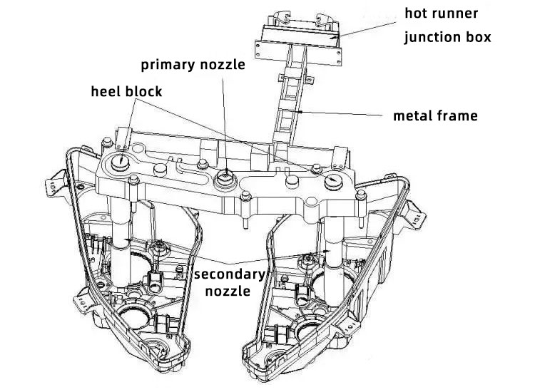
The pouring system of this mold adopts hot runner direct feeding. The feeding point is designed on the surface of the plastic parts, which facilitates the flowing speed of the material, shortens injection molding cycle, and improves the molding quality. Since the lamp shell is non appearance parts, ad the feeding marks on the surface does not affect its appearance. Figure 11 demonstrates the hot runner pouring system of the mold, which is composed of the junction box, primary nozzle, secondary nozzle and hot runner plate.
Design of side pulling core structure
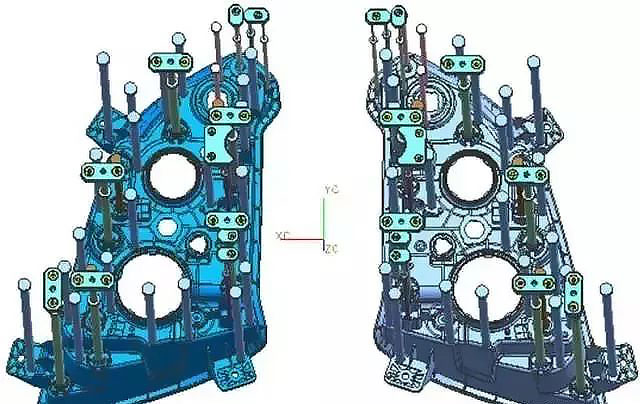
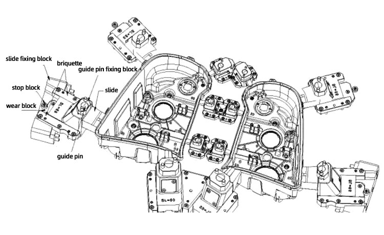
Each plastic part has 6 undercuts and the side core pulling of is composed of the six side core pulling structures, S1,S2,S3,S4,S5,S6, each of them adopts the “moving die slide + inclined guide pin + positioning fixture” structure, composed of Sliding block 25, inclined guide post 27, inclined guide post fixing block 36, locating clip 26, limit block 39 and wear block 28. See figure 12. This structure is easy to operate and the core pulling is more stable and reliable.
Setting the mechanical driven structure as the priority in designing slides because it is the most reliable and stable, as well as save cost. The design principle of slide is:
1. Start from right side. The upper and lower sides are the secondary choice. The upper side requires the spring or position to locate the clamp positioning. The slide at the lower side does not need spring because the slide will fall off due to the gravity. Thus, the design of positioning fixture can replace the spring.
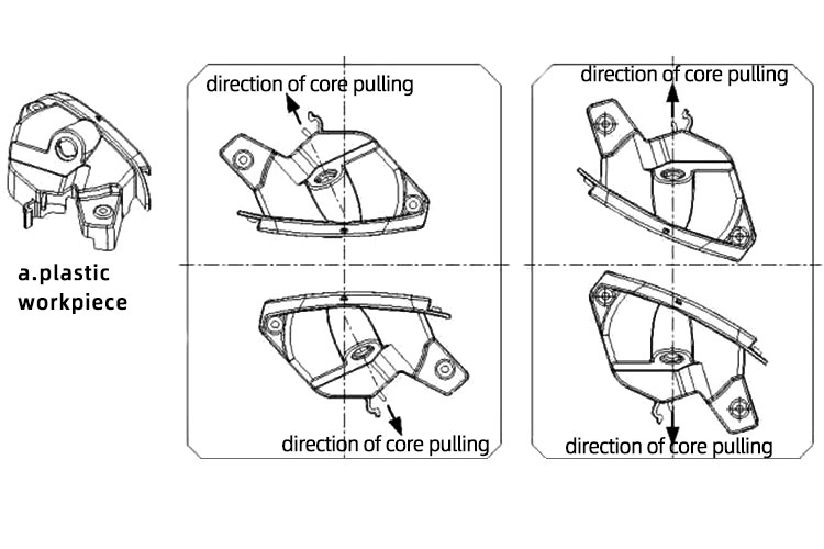
2. The conventional slider is preferred, and the oblique slider is selected for the second time. Since the processing difficulty of side and cost are high, as well as the complex structure, regular slides are safer. When arranging the plastic parts, we should avoid to produce a core pulling angle between the slide and inclined roof (interference). This reduces the mold processing difficulty. See figure 7, in which the slide is required to face up and right to pull the core. The machining difficulty is high. After the arrangement, the slide only need to pull the core upward, which is simpler.
3. The design of mold should follow the moving mold priority principle. The order of priority is moving mold, fixed mold, conventional slide, inclined slide, tunnel slide. The design of slide should ensure the minimal risks of slide and the plastic parts should not stick to the slide. The ultimate goal of processing is to aim for the simple operation and structure.
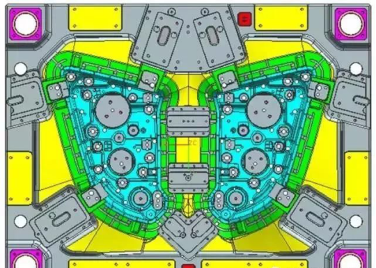
Temperature control system design
The size accuracy of the auto lamp shell is high, so the mold temperature control system should ensure the uniform and rapid cooling effect. To complete this point, the distance between the cooling water pipes and cavity surface should be almost equal to reach a uniform temperature in each area of cavity. Due to the big difference of the light appearance, the temperature control system of this mold adopts the combination mode “Vertical water pipe + spacer well”. See figure . The mold is sufficiently cooled with appropriate water circuit design and thus significantly enhances the production rate of plastic parts, which successfully limits the injection cycle within 40s.

The temperature control system of fixed and moving die of this mold is that 4 circulating waterways in the fixed mold, and 5 groups of circulating waterways in the dynamic mold. The following points should be paid attention to when designing the mold temperature control system:
1) the direction of the cooling water and material flow should be consistent. Th e cooling area should be at least 60 percent of plastic area (the area outside the plastic part is excluded).
2) the moving and fixed mold cooling circuits should be designed into cross grid form. The cooling circuit forms a intercrossed water net, which can cool the plastic workpiece uniformly.
3) when the condition does not allow the intercrossed water circuit, the water circuit of the fixed and moving mold has interactive clearance.
4) each cooling water contain as much as four water circuits to prevent the cooling effect being affected by the long distance water circuit.
5)The design of the water circuit can be connected with the outer water pipes of another water pipes, which provides the convenience for the adjustment for the deformation and shrinkage. Through the water circuit to improve the defects of the plastic workpiece, which is extensively applied in the inner and outer plastic workpieces.
6) the distance between each water circuit should be 3.5~5 times that the diameter of the water pipes (typically around 50-60mm). The water pipes is generally 15-25mm far from the cavity surface, which is accurately determined by the size of the mold.
7) the distance between water circuits and push rod, inclined push rod, and inserts should be higher than 8-10mm to avoid the mis-drilling due to the long water circuit, large mold.
8) in the design of the automotive mold, the hot nozzles should be designed with a separate water cooling circuit, not intercrossed with other water circuits to reduce the heat loss in the hot nozzle area.
Design of guide positioning system
Install one D60*445 circular guide pin on four corners of the mold. (The longest guide pin can be 10 times that diameter) the guide pin is installed on the side of the fixed mold. Since the plastic workpiece stays on the side of moving mold after mold opening, the release of workpiece will not be affected and it also avoid the workpiece being polluted by the grease on the guide pin.
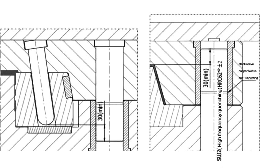
Another function of the guide pin is can work as a stow to fit mold. See figure 16, the length of the circular guide pin should ensure the guide sleeve is inserted when the inclined guide pin is inserted 20mm into the slide, otherwise it will bring troubles to the mold manufacturing and production, even damages mold. The design of the guiding system of the mold cannot work without the consideration of the design of tertiary positioning, especially the plastic workpieces of the automotive. The inappropriate guiding system design will lead to un-smooth movement. The damages of mold, dislocation of fixed and moving mold, segment difference of plastic parts and other issues are essential in the injection mold.
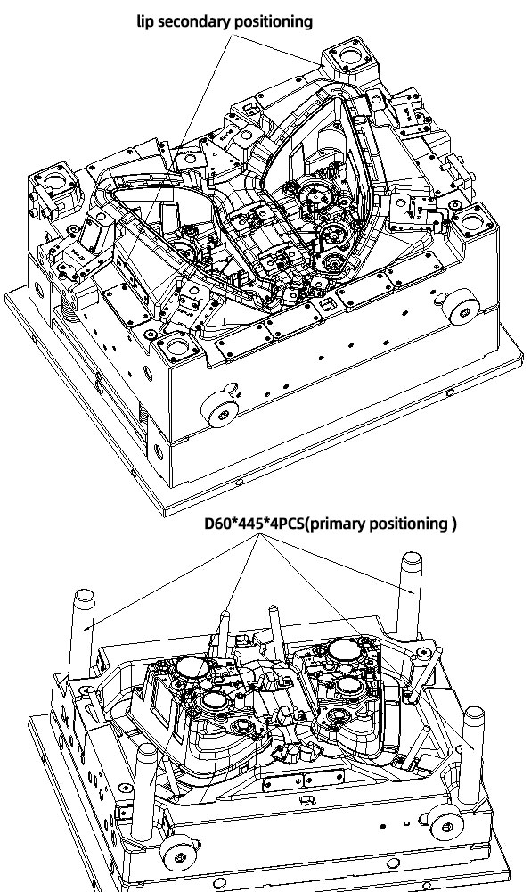
The primary positioning refers to positioning of the guide pin of mold, the primary positioning. It works by the coordination between the guide pin of the fixed and moving molds to complete the positioning of the fixed and moving mold. The positioning accuracy determines the processing accuracy of the mold base holes and the size accuracy of the guide pin and guide sleeve. The inaccurate mold base hole will lead to the guide pin burning. The guide pin is also the main component that bears the weight of the mold base. In designing, we should also consider the strength and length. Too long or too weak guide pins will also cause the inaccurate positioning and guide pin burning issue. Based on experience, the longest length of the guide pin is 10 time that of its diameter.
The function of the guide pin and sleeve can be concluded into 3 points.
1. Accurate guide and positioning to the movable parts.
2. Support the mold weight
3. Protect the mold molding parts
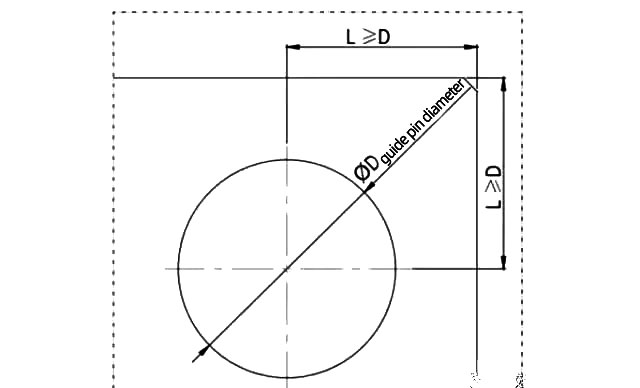
Typically, the length of the diameter is according to the standard LKM. The diameter of the non standard mold guide pin can follow the LKM standard. The design of the position can follow the guides in figure 17. The longest diameter of the guide pin is around 80mm. The length of guide pin should ensure it is 30mm higher than the highest surface of the mold. Mold with slides should enter into the guide sleeve 20mm before the guide pin inserted into the slide. See figure 18.
In the process of injection molding, it is necessary to keep the maintenance and lubricate to the guide pin and sleeve to avoid the friction of the guise pin and sleeve. The un-tightening of the camping mold and the non-parallelism of the front and rear plates of the machine platform are also the reasons for the inaccurate positioning and burning of the guide pin. In conclusion, the primary positioning is essential.
The secondary positioning refers to the interlocking positioning of the mold lip and the fixed and moving mold with four sides. The secondary positioning is mainly the positioning of the mold base. The positioning accuracy is higher than the positioning of the guide pin and sleeve. The groove of wear resistance block on the seam should be machined as much as possible to ensure the coordinating accuracy of the fixed and moving mold. The wear resistant block is made of heat treated material Cr12. The friction surface of the wear-resistant block should be lubricated with oil grooves. The wear-resistant block can effectively protect the weak S/O surface on the mold. The secondary positioning is significant for precision molds and automotive molds. The S/O surface of the mold is likely to cause the wear and burrs on the plastic workpiece. These requires special attention.
The three level positioning means the positioning of the designed seam on the core, which plays a role in mainly protecting the accurate positioning of the mold s/o surface. The positioning of the upper lip on the core is the accurate positioning of moving mold core, which can effectively protect the structure on the s/o surface. Meanwhile, it can also bears the side pressure of the injection molding, so one direction design is not suggested in designing. It should be interlocked to prevent the mold from tilting and sliding to one side, as shown in figure 19. When the lip is in the processing and mold fitting, its shut off is tighter than the mold core, so an appropriate process tolerance is required. We should try to use the lathe process accuracy to ensure the coordinating accuracy to avoid the manual coordination. This is essential for the automotive molds and precise molds. The height of the inlet should be 5-10mm higher than the top surface of core, for better protecting the mold core surface.
The three level positioning is more accurate than the primary positioning. The former is of great significance to the automotive molds and premise molds, which is also the key for the assurance of the plastic part quality and mold guide positioning. Also, it is applicable to other molds. If the plastic part does not have any shut off surface and appearance grain surface, the positioning design can be omitted. The rest requires the three level positioning and needs to ensure the accuracy.
Design of mold release system
The mold is a structure of “Push rod + push tube + Spring + pull reset”. The mold pushes the plastic part out by the push piece after the moving mold opening, the push piece fixture plate pushes the oil cylinder by the injection molding machine and return with the action of four 4 reset rods. The ejector pin has plastic parts and the specification of ejector pins should be as less as possible. Try to avoid replacing the hot nozzles frequently. The design of the mold releasing system should pay attention to the below points:
1. all special-shaped surface push rods must has stop-rotation setting to avoid incorrect assembly. The surface of the ejector pin has a grid to avoid sliding of the push rod during ejection.
2. There is clearance on one side of the retropinhole (for small and medium-sized molds, the air avoidance is 0.5, and for large molds, the air avoidance is 1.0). The top of the retropinhole should be with tapping holes. For better processing and mold clamping, the diameter of the return pin should be higher than 20mm. The heel should be designed on the opposite of the return pin. The ejection hole of the injection molding machine should not interfere with the garbage nail and support pillar.
The demoulding mechanism of the injection mold uses the form of “push rod + push tube”. After the mold is opened by the fixed and moving mold and the core is pulled by the lateral mechanism, the plastic parts are pushed out by the mold pushing system. The fixed plate of the push piece is mechanically pushed by the injection machine through the KO hole and reset under the action of four reset rods.
The following points should be aware of when designing the demoulding system for automobile injection mold:
1. large scale mold (length and width exceeding 1400mm × 700mm) 6 reset rods and 6 push rod plate guide pins are required. A pressure block is required with a diameter 5mm larger than the reset rod at the contact position between the fixed mold a plate and the reset rod. Generally, the pressure block selects 45# (or S50C) surface nitridation treatment. The push rod plate guide post should be arranged near the push out element with large push out force (such as oil cylinder, reset rod, etc.).
2. limit posts are required in all automobile injection molds, which should be installed above or near the KO hole.
There is a push rod under some slides of the mold. To prevent the push rod and a plate from colliding with each other repeatedly during mold closing, a push plate first reset mechanism is designed for the mold: one ¢ 20×20 spring is designed under the fixed ends of the four reset rods. The big end hole of the fixed plate of the reset rod is 3mm deeper than the fixed end of the reset rod. The reset rod will be pushed forward 3mm more than the pushing part after mold opening under the action of the spring. This ensures the reset rod and the fixed plate of the fixed mold get contacted 3mm in advance during mold closing. Reset the fixed plate of the pushing part and the pushing part in advance to allow the pushing part to reset first.
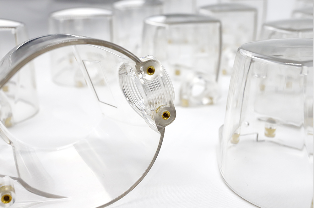
The sealing ring is required to the plastic rear cover hole and the left and right steering lamp head hole during the assembly of the plastic part.
The requirement for the sealing effect is high. Thus, no push rod is needed in this area as it may affect the sealing performance.

design of the mold base structure
The mold adopts four sets D60*445 guide pins and supports, so the mold strength is qualified. In the injection molding, due to the effect of the injection molding pressure, the strength of the mold plate is affected. Thus, besides the sufficient mold base strength, some auxiliary structural parts are needed to extends the mold service life and enhances the mold strength. The following points need to be aware of in designing.
1. To fit molds and easy operate, the mold has 6 process screws designed between the ejector pin bottom plate and clamping plate. The specification of the process screws is one standard bigger than the screws on the ejector pin plate. Engraving the “progress screws” next to the process screws because the process screws ought to be removed during the mold production. The purpose of doing so is to help the fitter easy recognize the screws. The limit pins should be positioned above or near the KO holes. More garbage nails are required at or near the bottom of the inclined top and the straight top, with a spacing of about 150mm.
2. the pressure bearing block on the mold parting surface sinks into the mold, and no oil grooves in the pressure bearing block and fine positioning. The edge of the pressure bearing quick groove mold frame should be at least 15mm away.
3. design of limit pin : the mold for mechanical ejection should be above the top rod hole; The mold for cylinder ejection should be near the cylinder.
4.stop pins are designed on the bottom plate. If the ejection system consists of two plates, fastening screws must be installed near the return pin to avoid deformation of the ejector plate.
5.Mold working process
The melt enters the mold cavity through the hot nozzle 33 of the injection molding machine. After the mold cavity is filled out, it has gone through the pressure holding, cooling and solidification processes until it is sufficiently rigid. The injection molding machine pulls the 13 movable mold fixing plate and the mold is opened from the parting surface PLI area. After 500mm of mold opening, all sliding blocks of the plastic part are separated from the plastic part under the drive of the inclined guide pins. The oil cylinder of the injection molding machine pushes the push piece fixed plate 22, and the it also pushes the push rod 16. Then the oil cylinder continues to act. After 75mm ejection, the plastic part is separated from the moving mold. After the plastic part is released by the iron hand, the oil cylinder of the injection molding machine pulls the push piece and the fixed plate to reset. Then the injection molding machine pushes the moving die to close the mold, and next injection molding starts.
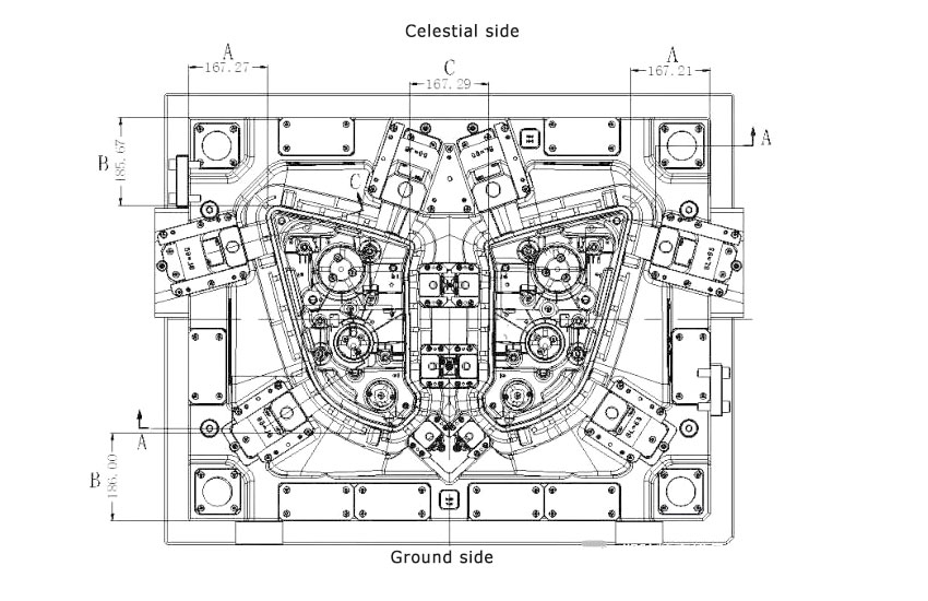
6. Design of mold strength and parting surface pipe position
The parting surface of the mold is designed on the moving mold, adopting four corner seam and four sides mode because it ensures reliable positioning and god strength. What’s more, the display of the mold is compact and suitable. In designing mold of automotive molds, the moving mold shut off angle should be higher than 7 degrees, at least 5 degrees. The reason behind this is that high shut off angle will largely extend the service life of molds. Meanwhile, it also minimizes the burrs issue. For area that is lower than 3 degrees, 1 degree fine positioning and 0 degree fine positioning cannot guarantee the accurate positioning of moving mold, so the shut off angle should be as large as possible. For medium and large scale molds, it is advised that the angle is higher than 7 degrees generally to ensure the service life of molds.
As shown in the figure 16, plastic injection molding manufacturers, like GREFEE, adopts two calculation methods, A and B size: first is to add 40mm sealing on the largest edge of the plastic part (In the automobile mold design, small mold (within 5050) uses 30mm seal, medium mold (5050-1010) uses 40mm seal and large mold (above 1010) uses 50mm seal), then add 50-70mm clearance (in the design of automotive molds, only the fitting of seal position, the rest area is clearance, reduce the working load of fit mold. Clearance is the area that ensures the mold strength). After that, plus the size of the bearing plate of the mold base parting surface is the size of A and B. Mold designed according to the above standard not only meets the needs of customers in mold strength but also saves the cost. The data of the C area is different due to the size difference of various plastic parts. The minimal dimension of the fixed mold at area D should ensure that the maximum part profile surface of the plastic part has a distance of more than 80mm. Due to the large injection pressure on the moving mold, it should be thickened accordingly. The minimum design at area e should be higher than 100mm to ensure the strength of the mold.
7.Design of the venting system of mold
The injection molds in automotive are usually large scale, so the design of the venting system is essential. Inappropriate venting system design leads to an array of quality issues, like the insufficient filling, gas trapping, un-smooth mold release, or even burning on the parting surface and other defects. The headlight shell of the automotive belongs to the inner functional parts. Appropriate venting system design is significant. The venting system is located on parting surface of this kind of mold. According to the characteristics of the plastic parts, installing the venting system on the moving mold will facilitate with the operation and processing, which can be directly processed with the CNC machining. The following points should be aware of in designing.
(1). the end of the material flow and the corner of the plastic part are the priority places to set the venting groove.
(2). close to the inserts and the thinest part of wall because it is easy to form welding marks here.
(3). it is optimal to set on the parting surface because the flash on the surface is quite easy to clean.
The venting system of this mold is on the parting surface on the side of moving mold. Shown as figure .
8. Result and discussion
It is easy for plastic parts of automobile headlight shell to stick to the fixed mold. The preliminary design prevention to fix the issue are as follows:
(1). Before the mold design, check whether the de-moulding obliquity of the area with large holding force of the injection molding plastic part is greater than 3 degrees, and try to design it at more than 5 degrees to avoid sticking to the mold and dragging the parts.
(2). designing the revers buckle patterns on the inner side surface of the large holding force and side that is likely to stick on the mold near the fillet of parts. The depth of the reverse buckle pattern should be 0.5-1mm.
(3). Reinforcing ribs are required on the inner side of the parts corresponding to the parts where the clamping force of the fixed mold is large, or the reverse buckle hook should be designed on the push rod.
In the design of this mold, the conditions that allow a smooth mold release is that the mold release angle of the area with large holding force is more than 5 degrees and a 0.5mm deep reverser buckle patterns. Thus, all the structures work smoothly and the mold is safe and reliable to use without sticking. It successfully fix the mold sticking issues that often appear on various lamp shell mold making process. After the trial production, the loading effect and the size all demonstrate an excellent performance. The modified lamp has been highly affirmed by customers in the auto show, creating appreciable economic benefits for customers.
MORE BOLG
Insert mold in injection mold service
What are advantages and disadvantages of Zinc alloy and Aluminum alloy?
Inspection standards for injection molded partappearance
How to judge the quality of your plastic products?
Inspection standards for CNC machining
To ensure that your products are 100% qualified
Categories

Try GREFEE now,for free
We keep your uploaded files confidential and secure.