Test mold injection molding processing guide and machining setting principles

Posted on : March 9, 2022 By GREFEE

This guide aims to better helping technological team members grasp knowledge of test mold injection knowledge and skills to quickly learn the guidelines of machining setting,
Can quick identify mold defects and continue improving
Helps you to quickly get involved into the injection molding production domain
Part1:Preparation before mold testing
Part2:Mold dry run
Part3:Injection volume formula
Part4:Injection balance
Part5:Clamping tonnage formula
Part6:Ideal clamping tonnage
Part7:Ideal holding pressure
Part8:Gate freezing
Part9:Ideal cooling time
Part10:Cooling water flowability
Part11:Mold temperature balance
Part12:Injection speed
Part1:Preparation before mold testing
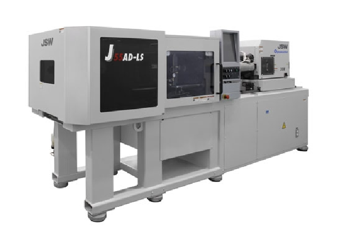
Injection molding machine selection and matching
- Injection molding machine selection and matching
- Mold length/width/thickness/location ring meet the target mold requirements
- Clamping tonnage, injection volume>30% of target mold
- Nozzle diameter, R corner 1 size smaller than mold size (mold R11 vs injection molding machine R10)
Preparation of materials
- Material specification (material temp/mold temp/baking temp), mold hydrographic map, product pic(volume/weight), mold cleaning detergent/mold dope
- Mold temp measuring instrument,water flow meter,micro-electronic balance
Part2:Mold dry run A
Inspections of mold open and close condition under low pressure: the mold open and clamping by fast, moderate, slow, three times. During the process, observes whether there is abnormal sound, interference, stutters. (fast-60%/moderate-30%/slow10%
Mold dry run B
IInspection of mold ejection system (low pressure):
1.The ejection is divided into three times, fast, moderate and slow. Observe whether there is abnormals
2.After the ejection pin on flat surface ejected, observe whether there is porosity or stuck
3.Ejector pin on slide side or ejector pin device, whether there is dowel pin(in case porosity or swivel)
4. Whether there is abnormal sound or shaking in ejecting (ejection pin or ejector)
Mold dry run C
Inspection of mold reset
1.Mold resets three times, fast, moderate, slow; observe whether can reset
2.After reset, lifter pin surface should not be 01mmm above the mold core or even with the mold core
3.Observe whether the limit switch contact is fine
4.Whether the ejector pin is interfered with slide doing ejection ( whether slide is reset)
5.Whether mold contains ejector pin return device (mechanical mode)
Mold dry run D
Mold slide movement inspection
1.Mold opening and clamping three times, fast, moderate, slow; observe whether slide moving smoothly
2.Slide returning smooth or not, whether is interfered with ejector pin
3.Slide location firmly or not
4.Conditions of hydraulic cylinder core pulling orders
5.Whether there are damages or stuck in DRY RUN
Part3:Injection volume formula
Injection volume V= π(Do1/2)²ST*damages
V: injection volume CM#
Do: screw diameter CM
CM injection stroke CM
Eg: screw diameter 44 mm injection stroke 45 mm
V= π(4.41/2)²4.50.98=67.27CM3
Injection weight G =Vηδ
V; injection volume η:specific gravity (density) δ:mechanical efficiency
Injection weight formula equals to cylinder volume formula
Part4:Injection balance
1. Constant injection molding 5 times and weigh the weight
2.Record weight of each component in each mold
3.reduce injection volume filling 20%, 50%, 90% samples, 3 times injection molding each respectively.
4.Weigh and record weight of each product above
5.If the difference between maximum product weight and minimum product weight lower than 2%, it is acceptable. —— if the weight difference is within 2%, means the injection balanced in cavity, otherwise imbalanced.
6.If it is single cavity mold, injection balance test is also needed (observing actual sol filling situation)
Part5:Clamping tonnage formula
Clamping tonnage F=PS=POK*S
P: cavity pressure is roughly equivalent to injection peak pressure
S: the maximum projected area of product
PO: ration of the flow distance and thinest wall thickness
K: material coefficient
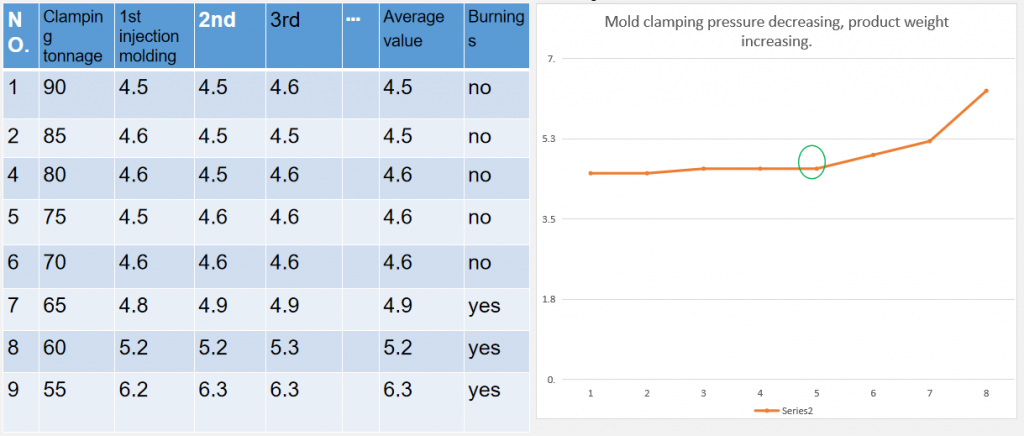
Part6:Ideal clamping tonnage
1.Take 90% of the maximum clamping tonnage, injection molding three times, records the weight of product each mold
Reduces the clamping tonnage by 5Ton and performs injection molding three times each, records the weight of product each mold till the weight being abruptly enlarged by 5% and there are burnings on edges.
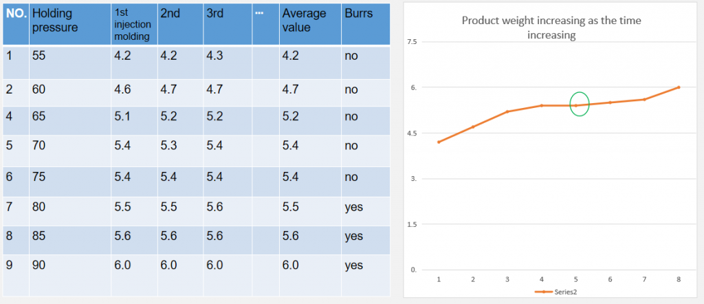
Part7:Ideal holding pressure
Methods to seek ideal holding pressure: sets a long holding pressure time and sufficient clamping tonnage, then increases the holding pressure from low to high and records in the table till the weight repeated and burnings appears. Record holding pressure .Product weight increasing as the time increasing
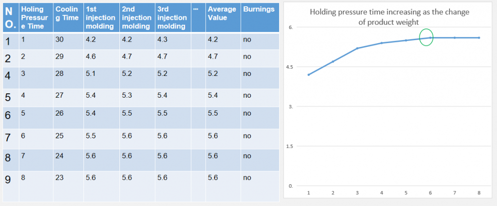
Part8:Gate freezing
Sets a high holding presser and set up the time as1 second and performs injection molding three times each. Shown as the table below, increase the time gradually and reduce the cooling time to maintain the whole circulation cycle.
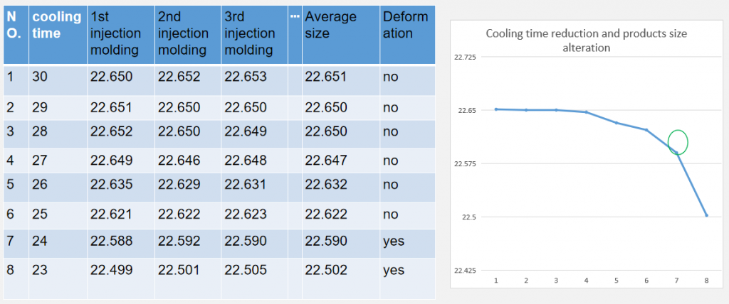
Part9:Ideal cooling time
- If the conditions of injection molding allows ( product filling finished ), estimate cooling time (first – long cooling time to make the product chilled thoroughly), injection molding three times, measure the dimension of the products.
- Record dimensions of products in table below, observe deformation of components.
- Product cooling time reduced by 1 sec one by one, injection molding three times.
- Reduce cooling time till the product deformation and size shrinking appear.
- Each product produced during cooling time should be 15 minutes after the components chilled thoroughly, then to measure the dimension.
- Evidence to confirm the ideal cooling time- stability of product dimension.
①based on experience, cooling time≥t(1+3t)…mold temperature below 60℃;(t the maximum product thickness )
②based on experience, cooling time≥ 1.5t(1+3t)…mold temperature above 60℃;
Select one area easy to measure and with big size as the target size
Ideal cooling time inside the mold cavity:
Cooling time reduction and products size alteration
Part10:Cooling water flowability
- Measured with Pressure gauge and flow meter and record the data and fill out the table
- Measures and records cooling water pipe diameter
- Finds dynamic viscosity value according to cooling water temperature
- Calculates the Reynolds number with formula below; Reynolds number (Re)=3160 ×cooling water volume/cooling water diameter × dynamic viscosity
- As only in turbulent state, the cooling water has high cooling performance (Re <2000 laminar conditions; Re >4000 turbulent state; Re=2000~4000 transition state)
| NO. | Cooling water diameter (cm) | Cooling water temperature ℃ | gpm Cooling water volume gpm | kg.cm² Cooling water pressure kg.cm² | Dynamic viscosity | Reynolds number |
| 1 | 0.096 | 23.9 | 0.25 | 3.0 | 0.9 | 7406.25 |
| 2 | 0.096 | 21.6 | 0.25 | 3.0 | 1 | 8229.17 |
| 3 | 0.096 | 21.3 | 0.26 | 3.0 | 1 | 8558.33 |
| 4 | 0.096 | 20.9 | 0.27 | 3.0 | 1 | 8887.50 |
| 5 | 0.096 | 19.9 | 0.26 | 3.0 | 1 | 8558.33 |
| Cooling water temperature | … | 18 | 19 | 20 | 21 | 22 | 23 | 24 | 25 | … |
| Dynamic viscosity | 1.0921 | 1.0921 | 1.0307 | 1.0000 | 0.9805 | 0.9610 | 0.9415 | 0.9220 |
Part11:Mold temperature balance
Utilizes mold temperature measuring instrument to measure mold core, the cavity select the temperature of 10 different points respectively, record in the right table.
The difference between actual temperature and average difference should not less than 2℃,if the value is over 2℃, it Indicates that the cooling effect is not equal and should be improved.
| location | Temperature |
| 1 | 59.5 |
| 2 | 59.1 |
| 3 | 56.5 |
| 4 | 58.2 |
| 5 | 58.3 |
| 6 | 61.5 |
| 7 | 58.9 |
| 8 | 58.0 |
| 9 | 57.7 |
| 10 | 57.5 |
| average value | 58.62 |
Part12:Injection speed
- Records hydraulic oil temperature (electric motor), molten material temperature and mold temperature
- Decide the sol end position by using first-degree injection only.
- Sets holding pressure and holding time as “0”, confirms the position of starting point of injection and then increases the injection speed gradually.
- Sets the injection speed to 95% and fills out to the position at 95% of rubber part (observe whether there is bedding material, keeps 2-6mm rubber pad amount.
- Records the highest injection speed when it fills to the position of 95% of rubber parts ( such as 95%)
- Record the highest injection speed and injection peak pressure in the “injection speed analysis table”
- Decreasing the injection speed gradually, increase injection pressure, observe and record the injection peak pressure when it fills to 95% of rubber part.
As the speed goes down, the peak pressure, molten material pressure, shear rate and other index go down respectively; injection time and relate viscosity increasing.
| NO. | injection speed% | injection time s | Peak pressure | molten material pressure | Shear rate | Relatie viscosity |
| 1 | 90 | 0.25 | 1000 | 11278 | 1.582 | 7444 |
| 2 | 80 | 0.41 | 980 | 10504 | 1.403 | 7620 |
| 3 | 70 | 0.65 | 940 | 10120 | 1.231 | 8369 |
| 4 | 60 | 0.75 | 930 | 10024 | 1.099 | 9642 |
| 5 | 50 | 0.78 | 920 | 9865 | 1.000 | 10520 |
| 6 | 40 | 0.80 | 880 | 9032 | 0.920 | 11880 |
| 7 | 30 | 1.5 | 820 | 8540 | 0.665 | 15560 |
| 8 | 20 | 2.8 | 700 | 7735 | 0.415 | 21620 |
| 9 | 10 | 4.9 | 610 | 7000 | 0.200 | 41240 |
Setting of Other critical values
The mold temp, material molten temp and dry temp should follow the material manufacturer’s practicing protocols, can be adjusted properly.
Feeding end position should follow the screw diameter and product weight/volume and adjust properly, no need adding holding pressure at initial adjustment.
The holding pressure switch position locates at when injection reach to 95%~99% (structural part 99%). VP switch time should be short and no spike waveform, can adjust properly according to structure.
Fast screw speed leads to material degradation and resets accuracy tolerance, the feeding time should not higher than cooling time (as short as possible)
Too small unclenching lead to drooling, too big unclenching lead to gas trapping, should be within an appropriate range.
For appearance product, can separate into sections properly (sections at turning area) and notes the speed adjustment. High speed and smooth surface butt also likely to cause material degradation and air bubbles inside product due to the increment of shear rate.
MORE BOLG
Insert mold in injection mold service
What are advantages and disadvantages of Zinc alloy and Aluminum alloy?

Inspection standards for injection molded partappearance
How to judge the quality of your plastic products?
Inspection standards for CNC machining
To ensure that your products are 100% qualified
Categories

Try GREFEE now,for free
We keep your uploaded files confidential and secure.