IThings you need to know about high pressure die casting.

Posted on : March 3,2022 By GREFEE
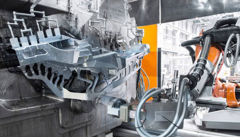
High-pressure die casting is known as a metal die-casting technique, which injects the molten metal by high pressure in the die casting machines and then injects the metal fusion into the mold cavity.
The mold makes of fine steel. Its working principle is as similar as that of injection molding. Most die casting components are iron-free, for instance, Zinc die casting, Copper die casting, Aluminum die casting, Magnesium die casting, Lead die casting, Tin die casting, etc.
According to different die casting types to select using either cold chamber die casting machines or hot chamber die casting machines.
The die casting technique is a good option for the volume production of metal for its high die casting production efficiency, low cost, and same quality effect as other methods. Therefore, high-pressure die casting is one of the most widely used casting techniques.
Features of Die casting:
Pressure casting is known simply as die-casting, which is a casting method that works by pouring molten liquid alloy into the shot sleeve and filling the cavity of steel mold fast to solidify the liquid alloy with the pressure for obtaining castings. Two things to distinguish die casting from other casting methods are high pressure and high speed.
1.Liquid metal fills the cavity under normal pressure and be crystalloid and solidified under higher pressure. Normal pressure range: 15—100MPa。
2.Generally, the Liquid metal fills the cavity insert extremely fast. It can reach a speed of 10-50miles/sec, sometimes over 80 miles/sec (linear velocity leading into cavity insert through the gate-gate speed). So, the filling time of liquid metal is real short, which is about 0.01—0.2 sec (changing upon the size of casting) can fill out the cavity insert.
Die casting is an accurate casting method. The die casting components have high accuracy of dimension and flat surfaces. In most cases, castings can be assembled directly without the CNC turning process, even for parts with threads that can also be produced straight away.
From small accessories, like the camera shell, e-cigarette shell, precisive devices, and decorations to complicated parts of vehicles, like autos, ships, planes, etc. All of the components used for these are from the die casting process.
High pressure zinc die casting process:
There are six steps totally in the die casting, including mold preparation, raw material melting, injection, parts cooling, parts ejection, and trimming. At the beginning of the production, spraying the lubricates into the cavity as the lubricate not only helps with controlling the mold temperature but also separates parts from the mold, and then the mold can be closed and injected the molten metal into it through the pressure of the die casting machine tup. The pressure range is around 10 – 175Mpa.
When the filling finishes, the pressure will continue until the casting solidifies, and then the ejector pin will eject the casting out. As one mold may have many mold cavities, it can produce many pieces of castings in each die casing process. It needs to separate the residues in trimming, including gate, runner, slag trap, and burrs.
This process is achieved by a special trimming mold die casting part. Other trimming methods include cutting with a saw or grinding. If the gate is fragile, we can beat the casting straight away, which is also labor-saving.
High-pressure injection fills the cavity insert at an extremely high speed so that the molten metal can fill out the whole cavity. In this way, the thin wall place fills out successfully. However, it would lead to an air trap as the inadequate ventilation due to the high-speed injection.
Most die casting components can not be finished only once, needing to rework to complete structures that cannot achieve by die casting, such as a tapping hole, an inner groove, etc.
The next step after the machining process is the inspection of defects; common defects include the retention (insufficient pouring) and cold shut. These defects might cause by the low temperature of the cavity or molten metal. Other factors, like impurities hiding in metal, too few ventilate holes, too many lubricate, etc. Other defects like air holes, shrinkage cavities, cracks, and flow marks. The flow marks result from gate defects, sharp corners, or too many lubricates left on the surface of parts. For more die casting defects, please check << GREFEE usual die casting defects and solutions>>
Usually, the die-casting machine has two types. They are the hot chamber die casting machines and cold chamber die casting machines. Their difference is the bearing weight. The typical pressure range is from 400 – 4000 tons.
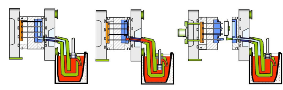
Hot chamber aluminium high pressure die casting
The metal state in the Hot Chamber Die Casting Machine is liquid or semiliquid. The metal is injected into the mold by stress. Each cycle starts, the plunger contracts while the molten material fills the gooseneck. The air pressure or hydraulic pressure plunger contract the metal to inject it into the mold. The upsides of the system include fast circulation ( 15times/min) easy achieve automatic operation.
Meanwhile, it also simplifies the metal melting process. While it cannot die-cast metals with a high melting point and cannot process aluminum die casting because the aluminum will separate the iron from the molten metal. So, the hot chamber die casting suits the die casting production of zinc alloy, tin, and lead. Besides, the hot chamber die casting cannot work out those large-scale die casting components. It usually goes for small die casting components.
Operating theories of hot chamber die casting machine:
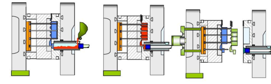
Cold chamber die casing
When the metal is not compatible with the hot chamber die casting technique, we can go for the cold chamber die casting, including aluminum, magnesium, copper, and zinc alloy with high aluminum content.
This technology needs to melt the metal in an independent melting pot and then transfer the molten metal to an unheated injection room or injection nozzle.
Eventually, injecting the metal into the cavity through hydraulic pressure or mechanical pressure. Cold chamber die casting machine divides two types, standing and horizontal.
A standing die casting machine is usually a small one, while die casting machines have diverse big and small models. So far, the largest horizontal die casting machine is from Tesla, which has an 8800T die casting machine for its whole carrosserie.
Working principle
Dos and don’ts of high pressure aluminum die casting products designing
1.Wall thickness design of die casting components
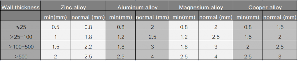
The quality of castings can be significantly affected by the wall thickness, for instance, aluminum alloy. Its thin-wall model is more rigid and compact than its thick wall model; Thus, if the rigidity and strength of casting are guaranteed, it should reduce the wall thickness as much as possible and make equal wall thickness.
When the wall of casting is too thin, the metal can not be fused successfully, which might impact the strength of casting and bring difficulties for the shape-forming at the same time.
Whether the wall thickness is too thick or unequal will lead to cracks or shrinkage. The strength of casting will be affected as wall thickness gets larger. Defects like the air holes inside the casting parts or shrinkages will increase.
The range of wall thickness of die casting is 2.0~4.0. Components whose max wall thickness is over 15 mm should not use the die-casting technique. The suggested min wall thickness and wall thickness value see the chart below:
Fillet in Die Casting Design
All sections of castings crossed should be fillet (cross-sectional excluded), as it enables the metal filling to be processed smoothly and helps with the ventilation. What is more, it can avoid cracks due to the acute angle. For the die casting components that need electroplating or finishing, the fillet should equally electroplate to avoid the residue around the sharp corner.
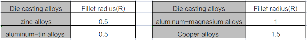
The fillet radius of zinc alloy should not be less than 0.5 mm. The fillet radius of Aluminum alloy and Magnesium alloy products should not be less than 1.0 mm.
The fillet radius of tin alloy should not be less than 0.5 mm, the fillet radius of copper alloy should not be less than 1.5 mm.
Calculation of casting fillet radius
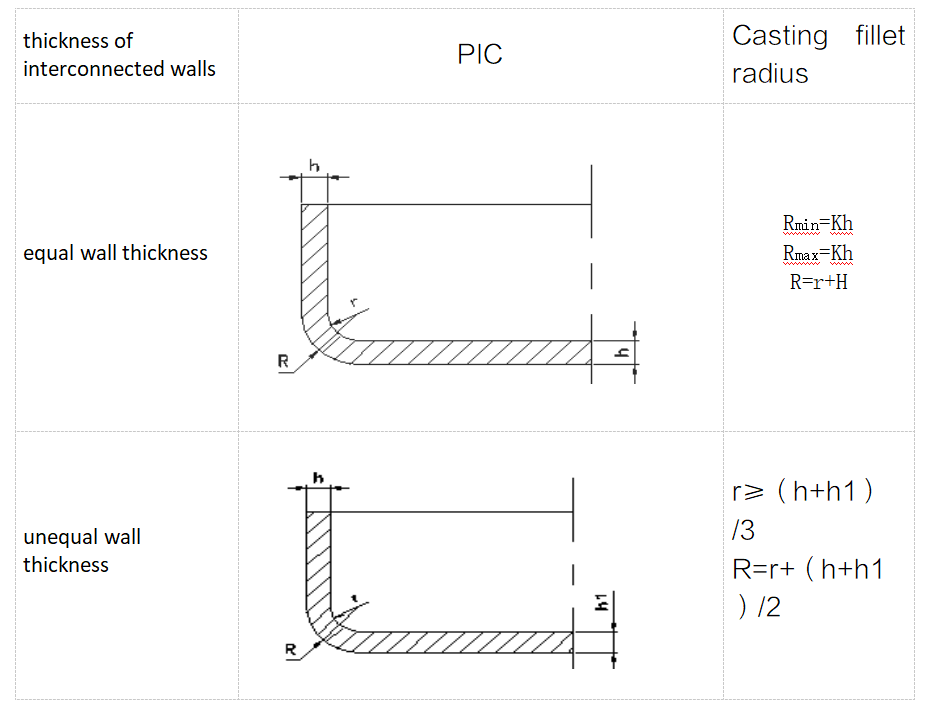
Description: zinc alloy castings: K=1/4;aluminum-magnesium alloy K=1/2。
Note: the size of the least fillet after calculation should not be less than the minimum value above.
Design of die casting de-molding angle
In the design of die castings, it needs to have a de-molding obliquity angle when designing, for the sake of convenient de-molding, reducing the posing force, core pulling force, and mold loss. Besides, it should have an angle as big as possible in structure to reduce the friction between the die casting components and molds. This method is more convenient to separate the parts from the mold with good surface quality. Besides, the obliquity angle direction should be the same as that of the de-molding.
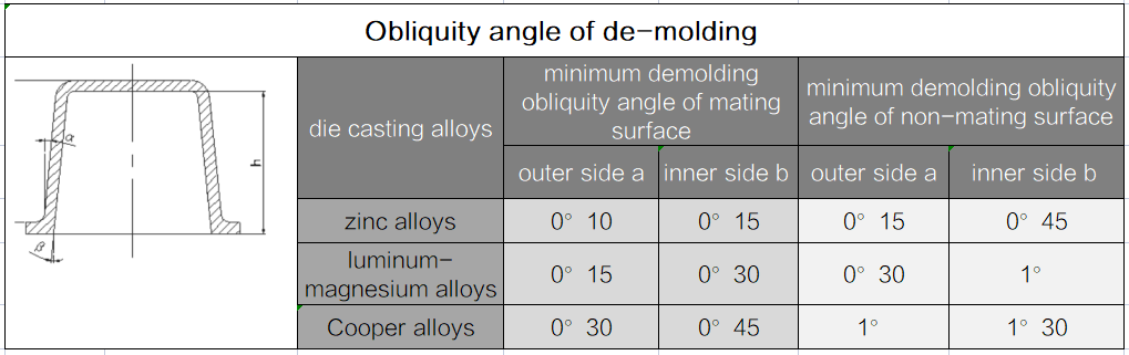
Description: ① casting components dimension tolerance caused by the obliquity angle, should not be included in the dimension tolerance value.
②: The value in the table is only adopted when the depth of cavity and height of core ≤50mm, the surface roughness is Ra0.1, the minimum value of one-sided tolerance of the big end and the small end is 0.03mm. When the depth or height is> 50 mm, or the surface roughness is over Ra0.1, then can increase the de-molding obliquity angle.
The de-molding angle currently being used is normally 1.5°.
Design of Die Casting Stiffener
Stiffer enhances the strength and rigidity of the components. Meanwhile, it also improves the manufacturability of die casting.
Note:、
- distributed equally and symmetrically.
- there should has fillet at the casting components connected bottom.
- avoid multi-stiffer crossing
- width of stiffer should not be larger than the thickness of the wall that is connected with. Wall thickness < 1.5 mm, stiffer using is not suggested.
- The de-molding obliquity angle of the stiffer should be bigger than the allowable value of the casting component cavity.
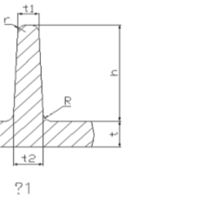
Normal size of stiffer, see pic 1:
t1=2 t /3~t;t2=3 t /4~t;
R≥t/2~t;
h≤5t; r≤0.5mm
(t—wall thickness of die casting components,maximum value no more than 6~8mm)
The minimum distance between the holes and edges in die casting components.
1.cast holes
The aperture and hole depth of the die casting components can be produced directly for holes without high requirements. See table 5:
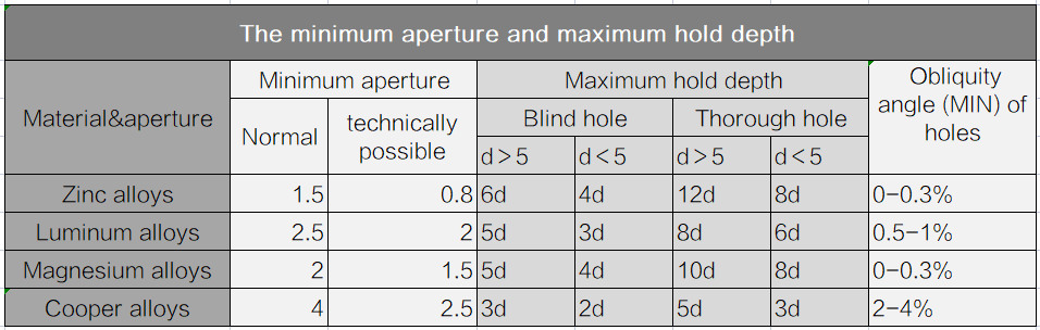
Description:
①. the index of depth in the chart is for the fixed core. Properly increasing the value for the single moveable core.
②.for large aperture and not high accuracy request, the hole depth is larger than the range mentioned in the chart above.
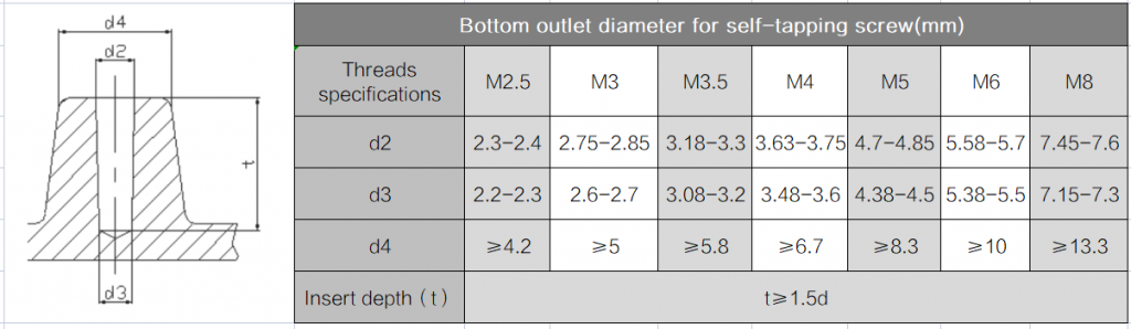
For the bottom outlet used by die casting self-tapping screw, bottom outlet diameter see table :
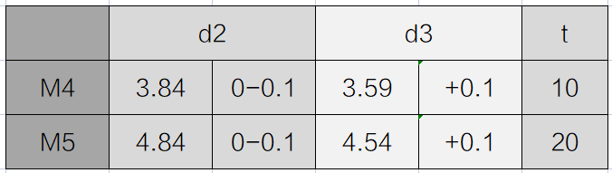
GREFEE frequently-used self-tapping screws specifications are M4 & M5, the bottom outlet diameter see table below:
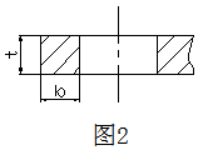
The minimum distance from the cast holes to edges
To ensure the casting components are shaped under good shaping conditions, there should be a certain wall thickness between the cast holes and the edges. See pic 2
b≥(1/4~1/3)t
Rectangle holes and slots on die casting components
Design suggestions of the rectangle holes and slots on die casting components, see table 7
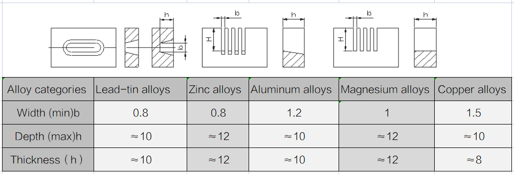
Description: b width has casting obliquity angle, values of small ends see table above:
Inserts parts inside the die casting components
Aims:
- Improve and enhance the local manufacturability of die casting components, like strength, rigidity, wearability, etc.
- Some parts are too complicated, like hold depth, inside concave cavities conditions that cannot perform core pulling.
- Few parts being casted as one
Dos and Don’ts of die casting components with insert parts
- The insert part must be connected closely with the casting components. Require slots, convex,knurling,etc.
- No sharp corners allowed for the sake of assembling and avoiding casting stress concentration.
- Must consider the stability of insert parts location on molds to meet the mold inside fitting demands.
- The metal layer of the outside insert parts should not be less than 1.5~2 mm.
- The number of insert parts should be controlled within range.
- If there is serve electrochemical corrosion reaction between the casting and insert parts, there should one protective coating on the surface.
- Casting components with insert parts should avoid heat treatment to avoid the volume change due to the reaction between two metals, making the insert part loosen.
Machining allowance of die casting components
When the dimension accuracy or appearance dimension tolerance is unable to meet the requests of product drawings, it should adopt machining processing methods, such as modifying, polishing, squeezing, molding, etc.
When it has to go with machine processing, we should select the small matching allowance. Besides, the blank sheet datum should be the surface that is not affected by the mold parting surface and molding.
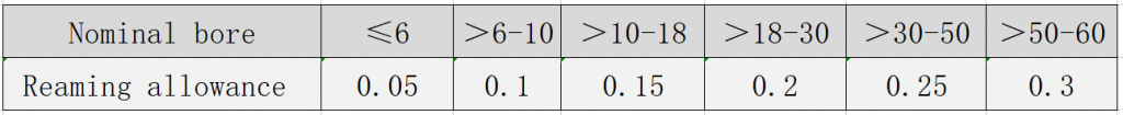
Suffused machining allowance and the tolerance see table 8, reaming holes allowance see table 9:
Table 8 suggested machining allowance and tolerance (mm)
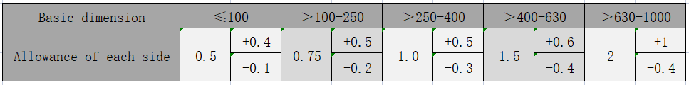
Table 9 suggested reaming holes machining allowance (mm)
Die casting mold:
The die casting mold consists of a cavity and a core. The area that connects the cavity and core is called the parting line. The moveable part includes a push bar and runners. The runner is a passageway between the gate and mold cavity. The runner works as access for molten metal to flow into the mold cavity.
The cavity connects with the front retainer plate of the machine, while the core connects with the moveable bottom retainer plate of the die casting machine. The mold cavity has two mold-cavity splits, mold insert, and mold block. They are independent parts and can be removed or installed easily from the mold by bolts.
Molds have specific design structures inside, so the casting parts will be left inside when open. By doing so, the ejector pin will push the core out by the push bar. The push bar is also called the ejecting rod, driven by the hydraulic pressure devices.
It properly operates all the push bars with the same strength to ensure the safety of casting components. When the part ejects out of the mold, the push bars are retracted and withdrawn to prepare for the next die casting process.
Due to the component being in high temperature during the de-molding process, so adequate ejector pins are the key to promise the average pressure on each ejector rod is lower enough not to damage the components.
however, the ejector pin still left marks, so it needs to check carefully to reduce the impact from the pin location to the component quality.
The slide inside the mold works for manufacturing undercuts. The slide in die casting will increase the cost of mold manufacturing but is a good choice for producing undercuts in complicated products.
Due to the temperature, the critical material property for mold is the thermal shock resistance and softness. Other characteristics include mold hardenability, machinability, hot cracking resistance, weldability, usability (especially for large-scale mold), and cost. The service life is directly associated with the steel, the temperature of the molten metal, and each circulation time.
Design experience of die casting mold
Products function satisfying is the priority. Other requests include proper designing die casting mold, simplifying die casting structures, lowering die casting cost, reducing die casting defects, or improving the quality of die casting components.
As the injection machining technology derives from the die casting machining technology, its design shares some similarities with rubber parts designing guidelines. For more details about die casting components design, click GREFEE die casting design guidelines.
Gating System
Requests of sprue for horizontal cold chamber die casting machine molds:
1.The inner diameter of the shot sleeve depends on the required pressure(%) and uniform distribution of the shot sleeve. Meanwhile, the inner-diameter tolerance of the gate sleeve should be a few millimeters higher than that of the shot sleeve, which avoids punch pin stuck or server friction loss resulting from misalignment between the gate sleeve and shot sleeve inner diameter.
Besides, the wall thickness of the gate sleeve can not be too thin. Moreover, the length of it is less than the ejection stroke of punch heads for the sake of blacking removed from the shot sleeve.
2.The inner diameter of the shot sleeve and gate sleeve should be finished first after heat treatment and then grind along the direction of the axis line. Surface roughness ≤Ra0.2μm.
3.The sprue spreader and the concave cavity which forming filler, the concave depth equals to that of runners and its diameter matches the diameter of the gate sleeve with a 5° obliquity angle along the direction of de-molding. When taking the coating-based injection sprue, it can increase the fullness of the shot sleeve as it shortens the volume of the effective distance of the shot sleeve.
4.Runner gates of the horizontal cold chamber mold locate at the upper area of shot sleeve, 2/3 inner diameter above. It prevents the liquid metal in shot sleeve from flowing into the funner earlier by the gravity and solidifying earlier.
5.The runner should be of a certain length and depth. The function of a certain length is for steady current and direct. If the runner is shallow, the temperature of the liquid metal would decrease quickly. If the runner is too deep, it could lead to slow condensing. This not only impacts the production efficacy but also leads to more returns.
6.The cross section area of runner should be larger than that of gate to make sure the metal filling speed. The cross section area of main runner should be larger than that of other branches
7.Both sides of runner bottom should be fillet to avoid crack at early stage. Both sides can have 5° angle. Surface roughness of runner ≤Ra0.4μm.
8.It should not seal the parting surface immediately after the liquid metal fills the cavity. The overflow well and venting well should not be against the core. The liquid metal should flow along the ribs and radiator.
9.The location of the gate should be where that has the shortest liquid meal stroke. When using a multi-strand gate, to avoid defects like vortex air trapping, oxidation impurity, it needs to prevent them from joining together and lashing.
10.The gate of the thin wall components should be smaller to ensure the necessary filling speed. The gate device should be convenient to remove with the circumstance of not harming casting components.
Overflow well
- Overflow well should be removed easily with the circumstance of not harming casting components.
- It needs to be aware that the location of the venting well on overflow well, as if the venting well is stuck early, it might affect the function of venting well.
- Multi-overflow gates or too brode and thick overflow gates are not allowed to be on one overflow well to avoid the cold fluid, residue, air, blacking in metal returning to the mold cavity from the overflow well and causing defects.
Fillet
(including corner) the drawing sheet usually doesn’t contain the requests of fillet R2; however, they cannot be neglected in the designing process to prevent making the fillet into a sharp corner or too small size.
The function of the fillet is to prolong the service life of the mold, for it helps with the liquid metal filling, venting, and reducing stress concentration.
Besides, the die casting components should not have cracks or other defects due to the un-smooth filing in the fillet area.
Obliquity angle of de-molding
The artificial side groove is forbidden in the direction of de-molding ( side groove caused by improper de-molding methods, like drilling or chiseling at the time of mold testing because the part sticks inside the mold cavity.)
Roughness
The molding area and the gating system should be polished thoroughly following the de-molding direction. Due to the filling time (0.1-02.sec), the liquid metal flows into the gating system from the shot sleeve.
To reduce the metal flow resistance and pressure loss, it is necessary to keep a high level of surface fishing. Meanwhile, the heating and erosion conditions of the gating system area are awful, so the worse the surface finishing is, the area is more likely to be damaged.
Hardness of molding area
Aluminum alloys: HRC50° approximately. Cooper: HRC40° approximately. in the machining process, there should have a fixing allowance for the upper limit of dimension and avoid welding as well.
Flowability
Flowability refers to the ability that liquid alloys to fill and mold. The touchstone of the flowability is to see whether it can die-cast intricate components. In aluminum alloys, the eutectic alloys demonstrate the best flowability.
Numerous factors affect flowability, including the ingredients, temperature, metallic oxide, metal compounds, and other solid particles of pollutants in alloy liquid. The external factors are the level of the teeming temperature and teeming pressure.
In production, after alloy materials are checked without issues, it is also necessary to improve the processability of casting (mold venting & temperature).
Also, it increases the teeming temperature without harming the quality of casting components, with an exception of fusion technology(refined & slag removal) to ensure the flowability of die-casting material.
Dos and don’ts of die casting conditions
The three main elements of die casting production include die casting machines, die casting material, and die casting molds. It cannot process without a single one of them.
Die casting technology combined the three main elements to produce qualified components with good appearance, high quality, and a standard size according to the drawing sheets smoothly, orderly, and efficiently.
The melting temperature of the material, mold temperature in injection, and molten liquid temperature.
Lastly, it needs to modify the casting components to obtain qualified parts.
The die casting mold working temperature selecting principle:
- Mold temperature too low, loose inner structure, hard to vent, hard for shape forming.
- Mold temperature too high, mold inner structure compact, but the component likely to be sticky on the cavity inside and is hard to de-mold. The too high temperature will lead to the mold puff up, which affects the accuracy of dimension.
- The mold temperature should be within an appropriate range. After it passes the tests, maintain the temperature. Things that need to be aware of about die casting mold conditions can conclude into two aspects: ① the molten temperature of the material. ② liquid and mold temperature in injection.
Factors that affect mold serve life
Damages
In die casting production, due to the repeated cooling and heating cycles, the surface and inside of the molds are distorted, implicated, and cause constant cyclic thermal stress, which leads to secondary damaging and tenacity losses of structure. It then results in cracks and continual cracking development.
Once the cracks get enlarged, the molten liquid metal would fill in, and with constant mechanical force, all factors will deteriorate the condition. Thus, before manufacturing, the mold must be pre-warmed. Besides, the mold must be working within the proper temperature range to prevent the checking phenomenon because many molds are invalid due to the heat fatigue and checking phenomenon.
Fractures
Due to the injection pressure, the thinnest area of molds will have cracks, especially the marking and electronic machining marks haven’t finished, or the clear angle of molding will appear small cracks first. When it is a brittle fracture, the condition will deteriorate soon, which is quite risky in this situation.
To prevent it, one thing is to diminish all of the scratches, electrochemical machining marks even if it is the area of the gating system, the surface finishing should be performed thoroughly.
Besides, it also has a higher requirement for strength, plasticity, impact toughness, and fracture toughness, especially since the strength must be adequate to meet the service life requirement.
Erosion corrosion
As mentioned before, the commonly used die casting alloys are zinc alloys, aluminum alloys, magnesium alloys, copper alloys, and full aluminum die casting. Zn、Al、and Mg are active metal segments and are compatible with mold material. Especially, Al, it is easily caused mold corrosion.
The higher the strength it is, the corrosion resistance is better. If there are soft spots on the molding surface, the corrosion resistance will be affected.
Many factors might lead to mold invalid, the external factors (casting temperatures, mold pre-warm or not, water trace coating amount, die casting machine tonnages, die casting pressure, fast gate speed, cooling water did not synchronize with the die casting production, die casting material categories, and amount of Fe component, size of die casting components, wall thickness, blacking type, etc).
Internal factors: (mold material, strength of mold, rationality of mold structure designing, rationality of gating system, internal stress of mold machining, mold heating techniques, and all sorts of precision and finishing requirements).
If the mold is invalid early, then it needs to find out causing by which external factor or internal factor is for the future improvement.
In the production, the erosion-corrosion is likely to happen in the local area of mold, like gate directly scoured parts (core, mold cavity), and areas have low hardness can have aluminum alloy mucosa.
GREFEE use imported fine steel for mold production, such as 8407 and 8418 of ASSAB Global. Usually, the aluminum die casting mold’s life can reach 100 thousand mold times; zinc alloys and magnesium alloy die casting components can be 500 thousand times.
Die casting parts produced by GREFEE has a specific machining process that can lift the serve life to 200 thousand times. Zinc and magnesium alloys die casting components can reach to 1million times. Contact us for free technical and cost assessment for die casting production.Request a quote
Commonly used material for die casting
Commonly used die casting materials include zinc, copper, aluminum, magnesium, lead, tin, and lead-tin alloys. Besides, some special die casting metals, including ZAMAK, aluminum-zinc alloy, and US Aluminum Association approved: A380, A386、A360, A356, A390, and AZ91D magnesium. Features of all types of die casting metal include:
- Zinc alloy: zinc alloy is the easiest to die cast. It is economical for manufacturing small parts and is convenient for electroplating and performing other surface treatments. It also has high resist compression, high shaping performance, long service life.
- Aluminum alloys: lightweight, complicated manufacturing and high dimension stability for thin-wall die casting components, excellent corrosion resistance, good mechanical properties, high heat conduction, and high electric conduction. It can maintain a high level of strength even in high temperatures.
- Magnesium alloys: easy for mechanical machining, high ratio of strength and weight. It is the lightest die casting metal that can be applied to electronic products, like mobile phones, etc.
- Cooper die casting material: high hardness, excellent corrosion resistance, has best mechanical property among all of the die casting metals, friction resistance, the rigidity close to steel.
- Lead-tin alloys: high intensity, extremely high dimension accurate, can be used as specific components to resist corrosion. For the public health aspect, lead-tin alloys are not allowed in food processing and storage equipment. Lead-Tin-Antimony alloys (containing a trace amount of copper occasionally) to produce the man-made lead characteristics and gilding of Toppan printing.
The weight upper limit of Die casting components in GREFEE used aluminum, copper, magnesium, and zinc material is 85kg, 4.5kg, 40kg, and 34 kg respectively.
Details of the smallest section area and draft angle of all types of material, see table below, the thickness cross section < 13mm.
| Metal | Smallest cross section | Smallest cross section |
| Aluminum alloys | 0.89 mm (0.035 in) | 1:100 (0.6°) |
| Yellow metal & bronze | 1.27 mm (0.050 in) | 1:80 (0.7°) |
| Magnesium alloys | 1.27 mm (0.050 in) | 1:100 (0.6°) |
| Zinc alloys | 0.63 mm (0.025 in) | 1:200 (0.3°) |
Pros & cons of Die casting technology
Pros
1.High quality:
Die casting components has excellent dimension accuracy, depending on the die casting material. Typically, when the dimension tolerance is 2.5cm, the error is 0.05mm. 1cm that the dimension tolerance increment will lead to an extra 0.002 mm error. Compared with other die casting technologies, its component’s surface is smooth.
The minimum products fillet can be 1-2.5 microns. Compared to sand-casting, gravity casting, or low-pressure casting, it can produce thin wall thickness of the casting parts, like the wall thickness(Min) of zinc alloy, die casting is 0.3mm, the wall thickness(Min) of aluminum alloy is 0.5 mm; the diameter (Min) of die casting is 0.5 mm; pitch(Min) is 0.75 mm. All the structures can be die-cast, like coil, heating element, bearing surfaces with high strength.
2. Good economical benefits
Due to the pros, like accurate dimension and clean surface, it can be used directly without mechanical machining or minor machining process, which not only enhances the metal availability but also reduces a large number of machine equipment and time, at the same time, lowering its price.
3.High manufacturing efficacy
The manufacturing volume of die casting machines is high. Taking the large-scale die casting machine as an example, the manufacturing volume of 3500T cold chamber die casting machines is about 1000 times per day, and that of hot small chamber die casting machines can be 15000 times per day.
Cons
The major con of die casting is the limits of wall thickness to the products produced by high-pressure die casting technology (the normal range of wall thickness is within 15 MM).
In die casting, the liquid metal fills into the cavity in the form of high speed. Also, the flow pattern is unstable, which contributes to the air holes on components.
So, it should not have the pre-warm treatment. It is for metals with good flowability only.
Apart from that, high equipment cost is also one of them. Take one 1000T- die casting machine as an example, which charges 1.5 million dollars for one set.
It estimates that the total cost would be about 2 million dollars for all of the accessories together. So, when making large-scale die casting components, it suits volumes higher than 20 pics production. The higher the volume is, the more economical it will be.
GREFEE has been involved in the die casting industry for 17 years. We have grown from a start-up with one 200T die casting machine to a large-scale die casting company with 12 die casting machines (3500T Max), more than 200 numerical controlling mechanics, and annual revenue of 24 million dollars.
Application range & developing trend of die casting
Die casting is one of the most developed metal molding technologies. It is an effective method to achieve little or without cut scraps with a wide range of applications and rapid development.
Die casting components are no longer limited to automobiles and dashboard industries. It also proliferates into other industrial departments, like agriculture mechanics, machine tool industry, electronic industry, national defense, computers, medical devices, clocks, cameras, and daily hardware as many as dozens.
It also involves car accessories, furniture accessories, bathroom accessories, LED lights accessories, tools, telecommunication, kitchen appliances, electrical&electronic accessories, belt buckle, lockset, zipper, etc.
GREFEE is not only experienced in the common die-casting technology, but also achieves great breakthroughs in vacuum die casting, thin wall die casting, and dilute core die casting. Moreover, we are also proficient in the adoption of new technologies.
MORE BOLG
Insert mold in injection mold service
What are advantages and disadvantages of Zinc alloy and Aluminum alloy?
Inspection standards for injection molded partappearance
How to judge the quality of your plastic products?
Inspection standards for CNC machining
To ensure that your products are 100% qualified
Categories

Try GREFEE now,for free
We keep your uploaded files confidential and secure.