Things need to know about CNC machining from CNC rapid prototyping to small volume production

Posted on : April 13, 2022 By GREFEE
Things need to know about CNC machining from CNC rapid prototyping to small volume production
A great mold designer should also work closely with the frontline workers and have many questions from the considering and communication about the plan, especially considering how to make the components easier to machine. A perfect plan comes from the continual exploration process. Based on our years of experience, below are some tips for manufacturing and design
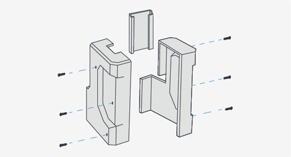
Simplify your design
Even the experienced design engineers and products developers will also make a common mistake, to complicate the components they designed. To un-mount the single-piece “super parts” with multiple layers into more simple parts. These parts can be connected by the bolt or glued closely. Unless there is a function need, we should avoid the surface treatment because it needs a ball nose cutter to process longer and more expensive machining. Try to design the components that cut from one side because this helps avoid a multiple-time operation and possible special jigs. Besides, this has to use a more expensive five-axis machining center or the one with the function of tilt rotation (3 + 2).
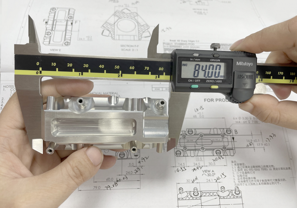
Take account of the components tolerance when needed
To make the tolerance more accurate than its requirement is actually not necessary. When the tolerance is higher than the number required, the mechanics will forcibly change the procedures or use special tools to carry out a second operation to fulfill the needs. It is optimal to just follow the “block tolerance” on the drawing sheet or consult the production manager on what is the best thing to do.
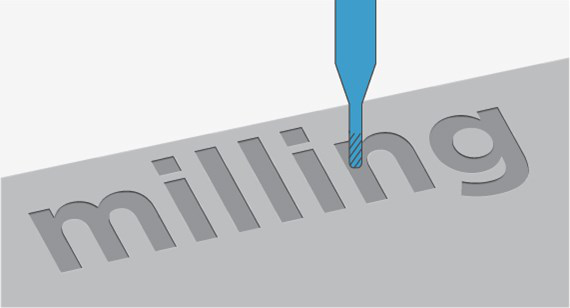
Avoid the text
The company name created by the machines looks beautiful, delicate, and can last forever but at an extremely high cost. Each character will need a micro cutter to track and much valuable time. There is even no need to try raised texture because this means grinding all the items which do not look like letters or numbers. Actually, you have other choices more than that, like laser cutting or rubber ink watermark.
Be careful with using deep processing and small-hole machining
The tools should be made of stiff and rigid materials, like tungsten carbide and high-speed steel (HSS).Even so, when there is a processing force, they will distort. This is becoming more and more troublesome. The further the tool extends from the tool carrier (depending on the operation), the “stickiness” of the carbide tool is about four times the tool diameter. This number could be more for soft materials. HSS tools will meet problems in the middle of this distance. This will cause shivering (ugly surging marks) and hard to achieve the tolerance of components and the service life. Lessons for designers: be aware of the deep and narrow grooves beside the high wall or the features of parts to prevent issues resulting from the distortion of tools.
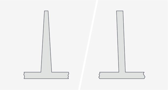
Be careful with thin wall components
Also, thin-wall components will have distortion. However, many machining materials are not as tough as the tools used to machine the materials. Thus, we need a rigorous rule for this type of component. Same, this depends on the features and the materials of the parts. One principle is that the design depth cannot exceed two times thickness. The walls’ thickness lower than 0.8mm will lead to deformation. You can consult GREFEE for solutions.
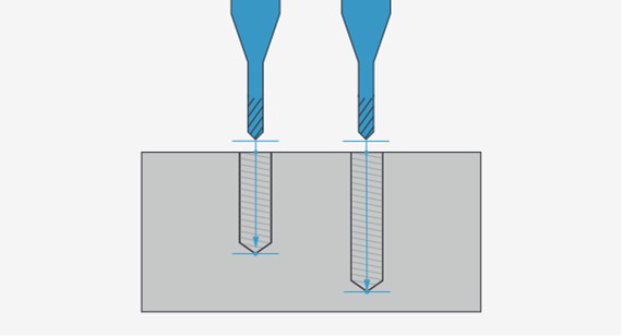
Deep drilling may be hard
Hole processing is the most common one among all of the operations. This process is often completed by drilling heads. These drilling heads may be different from what you can find in the hardware stores. With the holes getting deeper and deeper (like five to six times that of the diameter of drilling heads), it will be harder and harder to avoid the metal trash fragments generated during the operations. If you have deep holes in your product design and have a closer link with the diameter, you need to know that the more expensive the components will be.
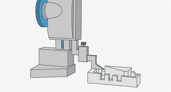
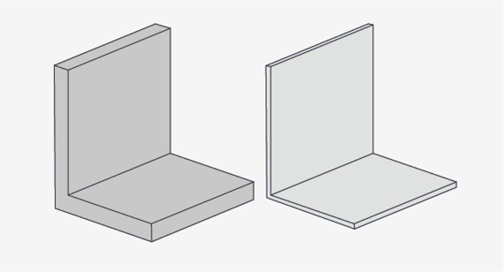
closed angle in turning area
In mechanical machining, it is hard to deal with the turning areas. This is like you are designing an electric cover for a product. You need a pocket containing a 2-inch circuit board on one side of the part. People who are not familiar with the practice might design a square corner pocket for the space, which is a bit bigger than the circuit board. This design has disadvantages because these square corners will increase the machining cost. The only way to process is to burn the EDM, the common machining technology in injection molding, rapid prototyping, and the mold industry. If the conditions and circumstances allowed, we can design an oversize pocket, and then we can use the end-facing tools. In this case, tools of 1/2 inch will be suitable. This means that we can add half of the diameter on the side of the circuit board plus extra space to adapt to the circuit board.
Another thing to consider is that deep grooves are taboo to the milling parts. Too deep grooves are hard to rotate. The long and thin axis is hard to spin, too. Using radius or undercut breakers to mill the edges of the parts is no big deal. However, there are some other steps that need to process on the milling parts. Some great ways to remove burrs include using the emery wheel, rolling in the sand, or blasting it with tiny glass beads or walnut shell fragments. Each method has its own advantages, which might affect the appearance or cost.
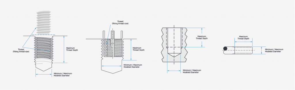
Design accurate threads
Manufacturing mechanical parts with threads is also a challenge. Internal threads can use a tap made by a cutting tool. It is similar to the bolt or fastener (called thread milling cutter). No matter which way, it is hard to make deep threads. The reason why is that it is hard for chip removal. In threads milling, it is radial cutting pressure. In general cases, the depth of threads that is two times the diameter provides sufficient strength to strengthen the integral performance of the threads, especially for the plastic parts. Finally, the tolerance of threads uses the “H” limit. The most common one is H2 or H3. However, the latter has a more strict tolerance. Thus, a higher cost. The optimal operation is to use H2 for all applications except the critical ones.
GREFEE has many years of experience in designing CNC parts. We are proficient in dealing with different components. Contact us if you want your project initiated with a competitive price and a bigger market.
MORE BOLG
Categories

Try GREFEE now,for free
We keep your uploaded files confidential and secure.