Stamping Process and Product Design

Posted on : Dec 17 , 2022 By GREFEE
Classification of Stamping ProductsProcess
1.Classification of Basic Operation
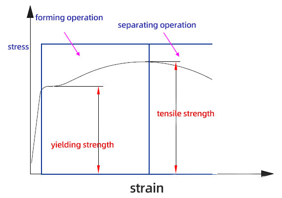
According to its deformation properties, stamping process includes material separation and forming.
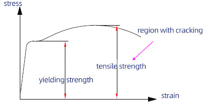
Separation means the blank will deform when it is under stamping force and the blank will be fractured and separated when the stress of deformed area reaches to tensile strength, then the workpieces of required shape and size are obtained.
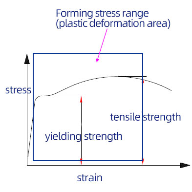
Forming process is a stamping process used to obtain workpieces of required shape and sizes. The stress of deformed area reaches the yielding point but not yet the tensile strength when the blank is under stamping force, so only plastic deformation occurs.
2. Categories of separating operation
According to different deformation principles, it includes blanking and finishing.
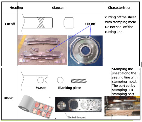
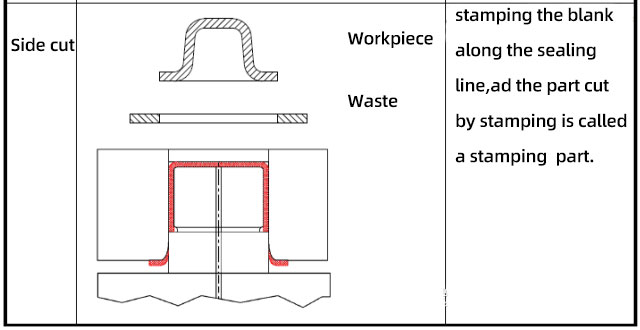
Blanking: It refers to punching the sheet metal along a certain curve or straight line with the die (including the following categories)
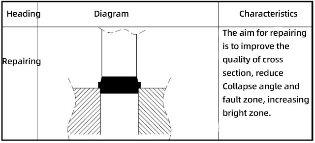
Repairing is a separation processing method used to re-process the section of the blanking part. Repairing is a kind of cutting principle, of which the dimension accuracy and cross-section quality are better than those of stamping parts.
3. Categories of forming processing
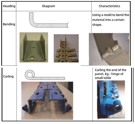
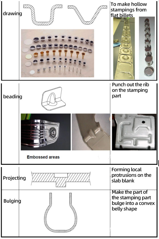
The forming process includes many steps, like bending, drawing, flanging, bulging and extrusion processes. (Details are as follows:)
Blanking
1. Introduction to the shape and forming process of blanking products
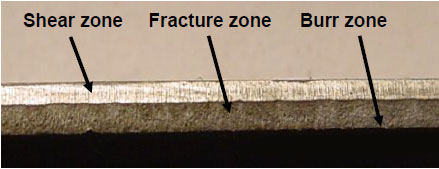
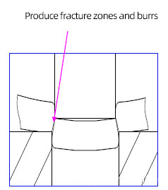
Shape of blanking products. The section of blanking products include: angle collapse, shear zone, fracture zone and burr that are produced under different stages, different parts and different stresses in the blanking process of products.
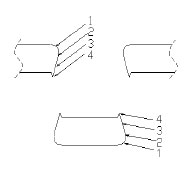
See figure above: 1. Collapse angle: height is about 8% ~15%T; 2. Shear zone: height is about 15%~55%T. 3. Fracture zone: height is about 35%~75%T. 4. Burrs: height is about 5%~10%T.
(1). Elastic deformation stage
Force analysis: part of material at cutting edge is under shear force. The force is smaller than the elastic limit. If the force disappears, the material will return to its original state.
State description: The male mold exerts pressure on the material, so the material is slightly squeezed into the cutting edge of female mold。
(2). Elastic deformation stage
Force analysis: The force applied on materials is from the edge to the center, gradually exceeding the elastic limit.
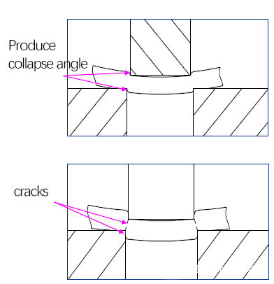
Description of state: male mold future getting into the material. The collapse angle and shear zone are generated during this stage.
(3). Shearing stage
Force analysis: the area of material close to the cutting edge of female mold should firstly reach the shear strength of materials, making the enlargement of cracks on material close to the cutting edge of female mold. While, part of materials of the cutting edge of female mold is still into the elastic deformation stage. With the pushing head further getting into the material, material close to punching head also reaches the shearing strength, and also cause cracks. After that, the two cracks overlapped and the material separated.
Description of state: the material get separated, when the upper and lower cracks overlap, they tear each other to produce burrs.
Key points of blanking process related to product design and design examples
1. Classification, function and structure of blanking products
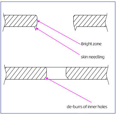
Aim: 1. Use for a general through hole (less required) 2. Used for self-tapping bottom hole (The product design requires a high proportion of bright belts) 3. Used as high accuracy shaft hole (no burrs and less fracture zones) (adopting mechanical de-burring methods or mold inversion method)
Note: When designing punching, due to the limitations of punch die strength, the size of holes should not be too small (generally larger than 0.5T)
Stamping
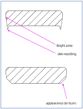
Aim: 1. Generally used for appearance (low requirement)
2. Used for butt joint laser welding assembly (without burrs, large shear zone, small fracture zone gap)
3. Used for soft decoration support (required curly edges or de-burrs)
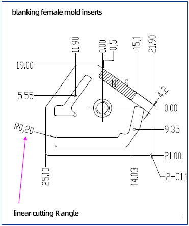
Note: 1. The design of products should make appropriate fillet at the connection of straight lines or curves of blanking parts (or the female mold is easy to be damaged due to stress concentration)
2. Considering the linear cutting process, the smallest R fillet of stamping parts or blanking parts should not be less than R 0.2.
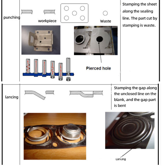
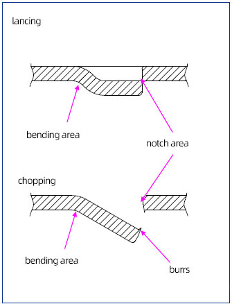
Lancing
Aim: 1. Used as buckles
2. Used as limitation
3. Saving process, increasing the utilizing rate of material and combine the two processes of trimming and bending into one. (disadvantages: the change of burrs cannot be changed, which has to be opposite to the direct of punching head).
Note: the The distance between the incision part and the bending part is far enough to meet up the strength of punching head .
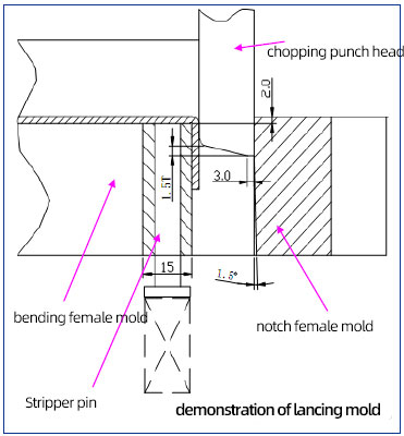
Points of lancing & chopping structure design
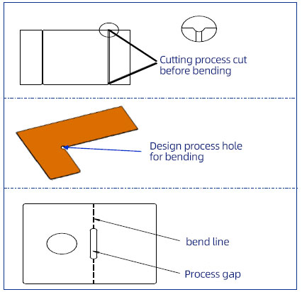
1) The punching head should be wide sufficiently when lancing. The design of parts should ensure the distance between notch area and bending area is more than 5mm, or the strength of punching head decreased, which further affects the life of mold.
2) The shearing part of cutting edges should ensure a 3mm straight side on both right and left when mold designing to in case of tipping. There should be break gap one both sides of punching head to ensure the it is cut before bending.
Summary of product design notice related to blanking
1)When designing products, the connection of each straight line or curve of the blanking part shall be properly rounded. (reason: 1. The smallest R of the ordinary linear cutting is 0.2, and the sharp corner is not ensured. 2. The stress concentrates at the sharp corners and female molds, so the mold is damaged easily under force.
2) When designing products, the direction of burrs should be noted clearly. Burrs are vital to the products assembly and safety of operators. (note: the direction of burrs not the stamping)
3) When designing stamping holes, due to the limitations of the strength of male mold, the holes should not be too small (generally is higher than 0.5T. Try not to make the hole diameter less than 0.8T)
4) During product designing, the tensile strength of material should be less than 630MPa as much as possible, or it is hard to make molds. (when the tensile strength of products is less than 630MPa, the mold material can be ordinary mold steel with relatively low price, such as Cr12, Cr12MoV, SKD11, D2, etc. when the tensile strength is higher than 630MPa, the mold material should be special and expensive mold steel, like SKH-9).
5) In product designing, if there are specific requirements for the blanking section, the accepted minimum value of each section should be noted clearly.
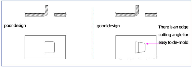
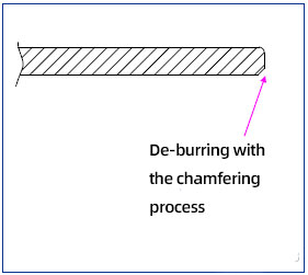
6) When cutting, the cutting angle on the products should be noted to facilitate de-molding and reduce the wear of the punch.
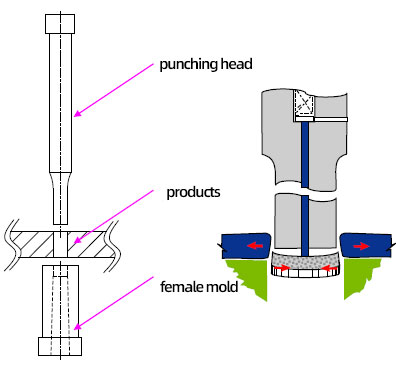
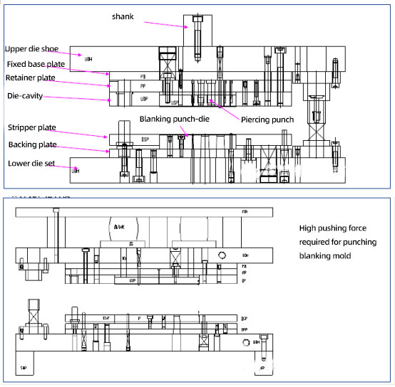
2. Introduction of stamping mold
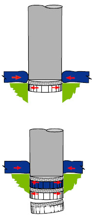
1) Punching and blanking mold
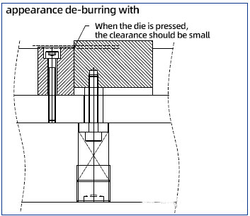
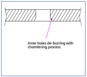
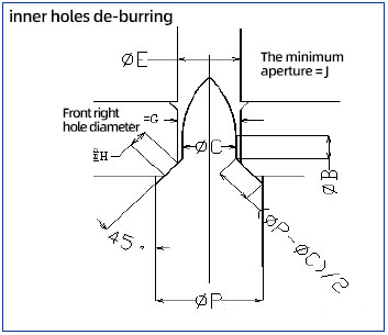
2) de-burring mold
3) Side punching die
Introduction to the shape and forming process of bending products
1. Form of bent products
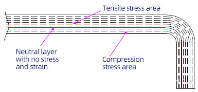
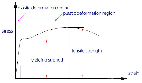
Bending forming mechanism: the stress applied on metal material should be higher than the elastic limits (yielding strength) but lower than the fracture limits (tensile strength), resulting in the curvature of the sheet metal in the bending deformation zone changes, and bending.
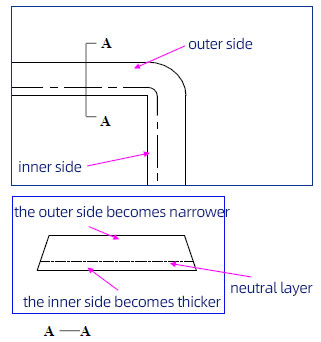
Bending stress analysis: when bending, the inner side of the material is subject to compression stress and the outer side is subject to tensile stress, and the tensile stress plays a leading role, so the neutral layer of the material is the material center that is inclined to the inner side of the bending.
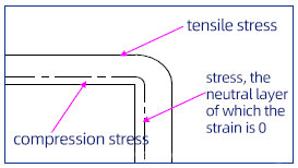
Neutral layer: about 0.255T close to the inner side of material
Outer firer of material is subject to the tensile force material, so it moves. The shortage of materials shall be supplemented by the width direction.
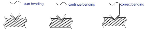
2. Bending process (taking V curve as an example):
1)the male mold contacts the sheet (blank), due to the different contact points of female and male molds, so the bending moment is formed. The elastic deformation occurs under the bending moment, causing the bending.
2) with the male mold continue going down, the sheet is gradually close to the surface of female mold, leading to a decrease in radius of bending and bending moment arm. The contact points of female mold and blank all moves to the two inclined surface of female mold from the two shoulders of female mold.
3) with the male mold continue going down, the two ends of sheet start bending when contacting the inclined surface of male mold.
4) flattening stage, with the clearance between male and female molds becoming narrower and narrower, the blank is flattened between the female and male molds.
5)Correction stage. When the stroke is over, correcting the blank to make the straight edge of the fillet fits with the punch to form the required shape.
3. Two issues that are most likely occur in bending products (rebound, cracking)
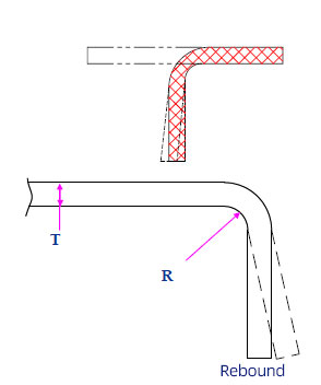
1)rebound
Cause: the material is arranged by multiple layers of fiber. The Each layer of fiber is under different stress conditions (the tensile stress of the outermost layer is the largest, and the compressive stress of the innermost layer is the largest. The magnitude of the two forces decreases toward the neutral layer). Thus, after the formation of bending, not all the fiber layers are subject to the force that is higher than the elastic limit of material. So, rebound exist when it is during the elastic deformation stage.
1) The stress and strain of the neutral layer are zero.
2) The internal compressive stress of the neutral layer increases gradually.
3) The tensile stress at the outer side of the neutral layer gradually increases.
1) when the stamping part bends, the strain of most material layers will go into the plastic deformation region, and these material layers will not rebound.
2) the material layer close to the neutral layer will still in the elastic deformation region, these material layers will rebound after the external force disappearing.
Factors affecting rebound:
(1) the higher the elastic limit of material is, the higher the deformation stress required, the larger the rebound is.
(2) the lower the relative bending radius of material R/T, the stress are more concentrated, the smaller the ratio of elastic deformation, the smaller the rebound is.
2) Cracking
Part of the material layer is subject the stress and when it is higher than the tensile limit, the workpiece will crack (the further away from the neutral layer, the greater the stress and strain of the material layer)
Methods to avoid the cracks: avoid bending, and make the R angle inside the corner small (normally R is over 0.5T)
4. Deformation characteristics of bending products
(1) The outer fiber of material is subject to the tensile stress, the material moves relatively. The shortage of materials is supplemented by width and thickness, so the width and size of materials are reduced.
(2) The inner fiber of material moves along to the direction of width due to the compression stress, causing the inner width expanding.
(3) When the width is less than 3 times the material thickness, it should be avoided as much as possible when the above phenomenon is evident.
5. Key points of bending process related to product design and design examples
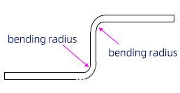
(1) The radius of fillet of bending parts should not be less than the minimum bending radium to in case the generation of cracking, but also cannot be too large, or the rebound will be large due to the incomplete deformation (normally the minimum bending radius R>=0.5T)
Note:
1) The bending angle R should not be too small when product designing, or it will cause stress concentration.
2) The size of R should be marked on the inner side (detailed reasons: when bending, the workpiece is close to the punch, and the R angle of the punch determines the R angle of the workpiece, which is easy to control and adjust.)
(2) The bending length of bending parts should not be too short, or it will be hard to obtain parts with accurate shape when the supporting length of mold to material is too short. The bending parts are more likely to outspread. H>R+2T.
Note: The bending straight edges should not be too short when product designing, or it will cause outspreading, which is hard to control the virtual angle.
(3) The bending parts should be located at the sudden change of part width to avoid tearing. If necessary, bending at the sudden change of width, the process groove shall be designed in advance.
(4) Since the slip phenomenon occurs more or less when bending. Therefore, process holes shall be designed as far as possible during product design.
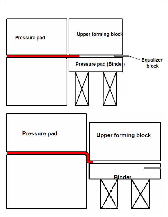
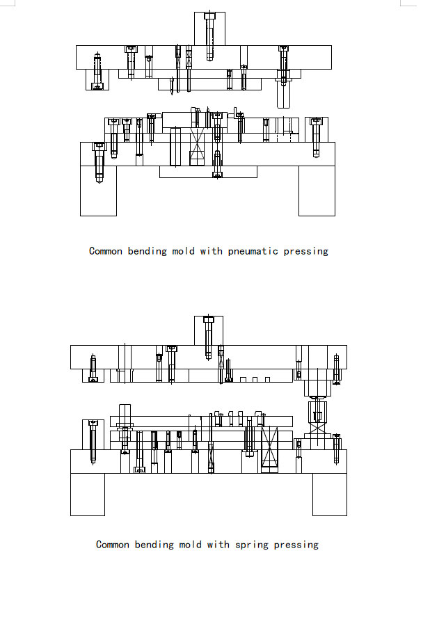
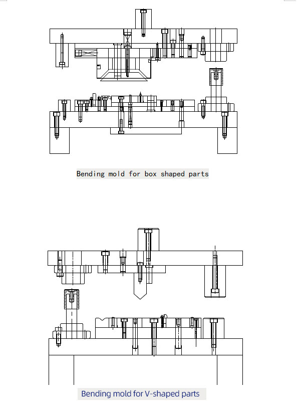
6. Introduction to bending mold
Introduction to Molding Process Form and Process
1. Classification and introduction of forming process
Forming principles: when the stress subjected to the material is higher than the elastic limits (yielding strength) but also is lower than fracture limits (tensile strength), generating the deformation mode desired by the designer within the plastic deformation range.
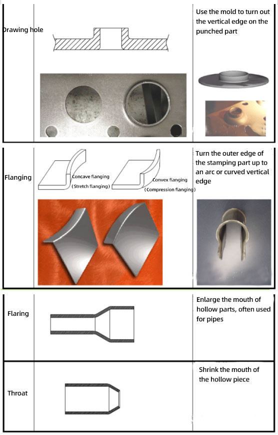
Forming process classification: 1. Drawing 2. Extrusion 3. Flanging 4. Hole flanging (hole drawing) 5. Necking and flaring
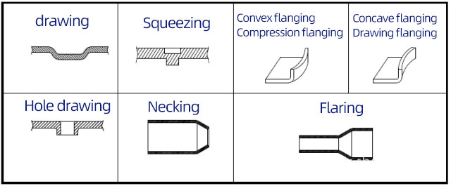
2. Key points of forming process related to product design and design examples
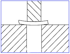
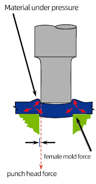
1) Squeezing
Convex closure squeezing functioned from three aspects:
(1) Used as a self guiding pin between two parts
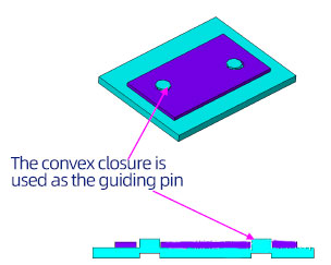
Note:
When the convex closure is used as a guiding pin, the diameter of it should be controlled strictly. Normally, the diameter tolerance should be within +/- 0.04mm.
Since the convex closure is made from squeezing, so the side of it is all shear zone.
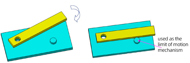
(2) Used as a limit for motion mechanism
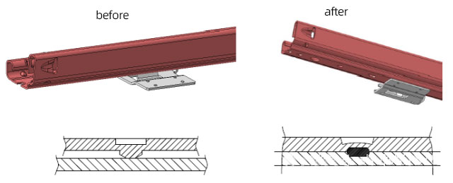
(3) Used as a bump for projection welding
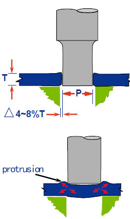
Notes for convex closure designing and size of punching head
Principle: 1) there should be sufficient material to connect between the convex closure and matrix, or the convex closure is easy to fall off. 2) the diameter of protrusions should be D>= 2t+0.7,and is more than 1.8mm when it is used for welding projection.
Height of protrusion H>=(0.4t+0.25),and is over 0.5mm
The design dimension of convex hull limit height is shown in the figure below.
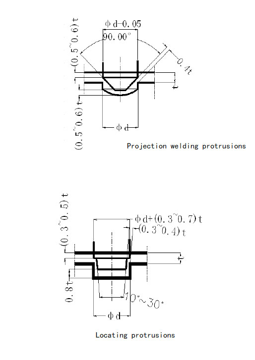
Note: when making the dimension of protrusions, the dimension of convex part can be controlled, but the dimension of concave part cannot be controlled.
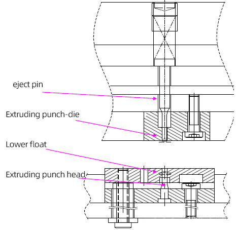
Mold structure of squeezing convex closure: the dimension of female mold decides the diameter of convex closure. The height of convex closure depends on the eject pin and extruding punch. Note: when marking the dimension of convex closure, the dimension of convex part can be controlled, but the dimension of concave part cannot be controlled.
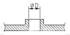
2) hole drawing
Two functions:
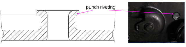
A)used for rivet connecting parts (including punch riveting and turn over riveting)
Advantages: saving rivets and costs
Disadvantages: cannot bear large pull out force or shear force.
Punching and riveting: used for fixation
Hole pulling and riveting: it plays the role of rotating shaft.
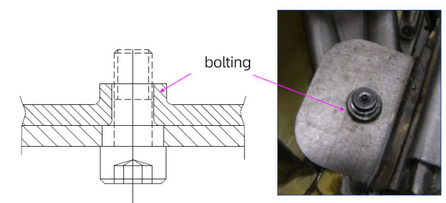
b) Used as coupling nut
Things need to know for hole drawing design and size of punching head
Principle: a) must have sufficient material flowing (the feasibility of hole drawing must be calculated)
b) Used as a rivet, the outer diameter of hole drawing must be controlled (outer diameter noted for dimension)
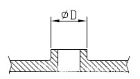
Note: the mold can control the inner and outer diameter of hole drawing. The punching head controls the inner diameter. The female mold can control the outer diameter, but cannot control them simultaneously, that is one part can only control one value.
c) Used as a bolt, the inner diameter of hole drawing must be controlled (inner diameter noted for dimension)
D) Used as a bolt, the thickness of straight edge after the thinning of hole drawing should be higher than 1.3 times of thread pitch.
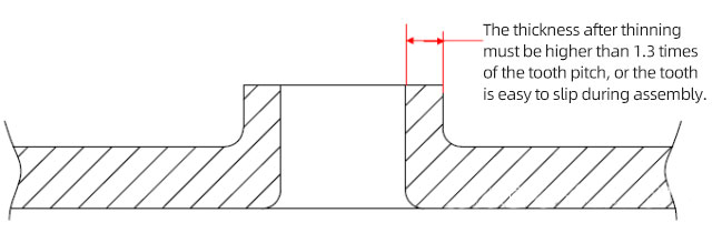
The thickness after thinning must be higher than 1.3 times of the tooth pitch, or the tooth is easy to slip during assembly.
e) There is a requirement to the strength when is used as a bolt, which must ensure the minimum height of straight edge shall be more than 3 times of thread pitch after hole drawing.
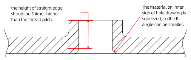
The height of straight edge should be 3 times higher than the thread pitch.
The material on inner side of hole drawing is squeezed, so the R angle can be smaller.
Hole drawing feasibility calculation:
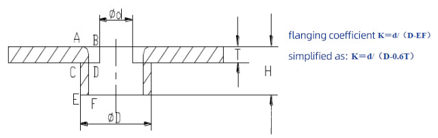
Hole drawing: The stamping process of turning the material into a side stand flange along the circumference of the inner hole.
Flanging coefficient: the ratio of the pre-punched hole diameter to the pitch diameter of the straight edge after flanging (the larger the flanging coefficient, the smaller the deformation degree)
Factors affecting flanging coefficient:
A) The plasticity of material, the better the plasticity, the smaller the flanging coefficient
B) The smaller the diameter of pre-punched holes, the smaller the flanging coefficient.
C) Processing methods of holes (if the flanging is higher, then the burrs are located at the inner side and is not easy to crack. When it is located at the outer side, it will require to guide face, then start the hole drawing.)
D) Modes of flanging punch (the spherical punch will decrease the flanging coefficient and worsen the deformation degree)
Theoretically, to judge whether the feasibility of hole drawing is according to the hole drawing coefficient (this method require multiple certain factors, consuming lots of energy and time). Normally, this can be known from the proportional relationship between pre punching and material thickness. When the relative diameter of pre-punched holes D/t is over 1, it indicates the feasibility is good.
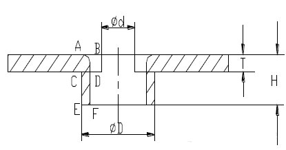
Calculation of the dimension of pre-punched holes
Principle: the volume before and after flanging shall not change.
AB={H*EF-(π/4-1)*EF*EF}/T
Diameter of pre-punched holes d=D-2*AB
Normally, the thickness of the material becomes thinner after flanging, and the thinning coefficient is taken as 0.45 to 0.9.
Thinning coefficient: the ratio of EF to raw material thickness T
Normally, when 当d>=T, it means the hole drawing is feasible (experience value, see the hole drawing coefficient for mored
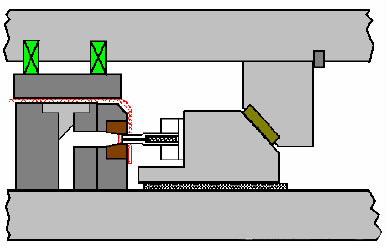
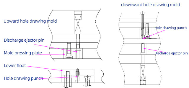
Structure of hole drawing mold
Structuer of hole drawing punch
A) When adopting parabolic shaped flanging punch, due to the arc transition, it achieves a high flanging quality (see figure below)
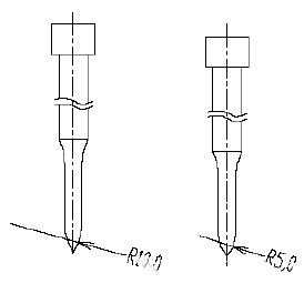
Note: when the radius of arc is different, the extrusion effect of punch on materials will be different, too. The small circular punch cause a large squeezing pressure at the moment when the material is squeezed, thus the material deformation is evident, too. Therefore, when other conditions are same, the flanging height of small arc flanging punch is higher.
b) One time flanging forming punch without pre-punching.
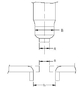
Note: the size of the acanthopore should be the same as the pre punching during double forming (A=a, B=b). The one-time punching and flanging structure is only applicable to the situation where the flanging burr is on the outside.
3) Concave flanging
Flanging is the process of turning materials into short side edges along the contour curve.
A)Concave flanging (extended flanging): deformation is similar to hole drawing.
B) Thinning rate ranges from 0.9 to 1 (the most severely deformed area is at the highest end face)
Measure the feasibility of concave flanging
A)Unfolding dimension
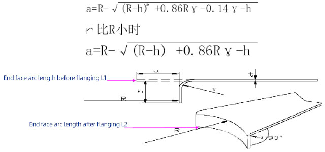
B) Tell

Cracking occurs when the deformation rate of end face K > the extending rate of raw material.
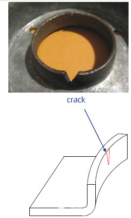
The value of R, r, h can be adjusted when designing products, making the deformation rate of end face meet up the designing requirements without cracking phenomenon.
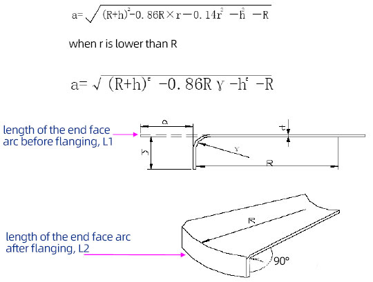
4) Convex flanging
a) Convex flanging (compression flanging): deformation property belongs to the compression flanging.
b) Development dimension of convex flanging
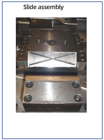
Introduction to other stamping die structures
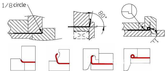
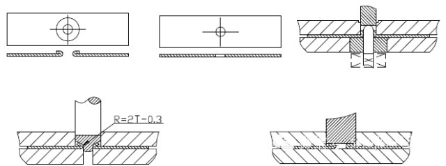
1. Rolling mold structure (form I)
Steps: 1. Roll an eighth circle 2. Diagonal upward for 80 degrees 3. Roll down the circle for forming.
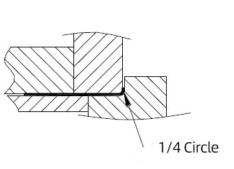
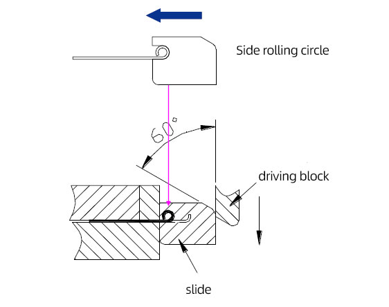
2. Rolling mold structure (form 2)
Steps: 1. Roll the quarter circle 2. Use the slider to push laterally.
3. Flattening mold structure (outer edge flattening)
Steps: 1. Blanking; 2. Upward curved 90 degrees; 3. Press down 70 degrees (the size of punch R is 2 times of the material thickness minus 0.3) 4. Flatten
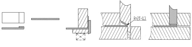
4. Flattening mold structure (inner hole flattening)
Steps: 1. Blanking; 2. Upward curved 90 degrees; 3. Press down 70 degrees (the size of punch R is 2 times of the material thickness minus 0.3) 4. Flatten
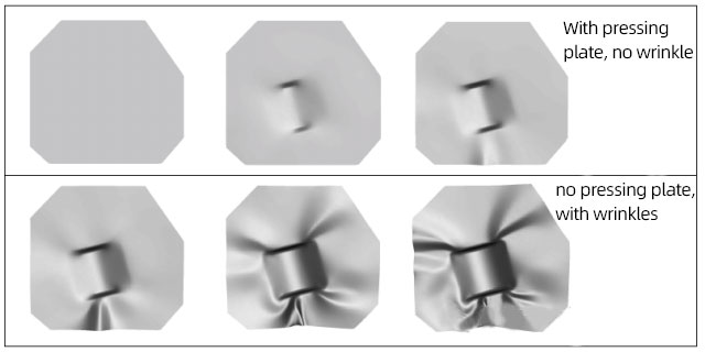
5. Drawing structure
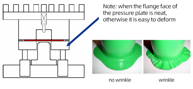
Note: when the flange face of the pressure plate is neat, otherwise it is easy to deform
MORE BOLG
Insert mold in injection mold service
What are advantages and disadvantages of Zinc alloy and Aluminum alloy?

Inspection standards for injection molded partappearance
How to judge the quality of your plastic products?
Inspection standards for CNC machining
To ensure that your products are 100% qualified
Categories

Try GREFEE now,for free
We keep your uploaded files confidential and secure.