Structural Design of Plastic Injection Parts – Wall Thickness

Posted on :Dec 21 , 2022 By GREFEE

Definition of wall thickness
Wall thickness is a basic structural characteristic of plastic parts. If the outer surface of plastic parts is called the outer wall, the inner surface is called the inner wall, then there is a thickness value between outer and inner walls. The value is called the wall thickness. The value entered when the shell is extracted on the software during structural design can also be said to be the wall thickness.
Function of wall thickness
For the outer wall of products
The outer wall of parts is like the outer skin of parts. The inner wall is the structural skeletons of parts. Different appearance effects can be achieved by surface treatment of outer wall of parts. The inner wall just connects the structures (ribs, screw bars, buckle etc.) together and enables a certain strength to the parts. In the meantime, other structures may be filled out during the infection molding process. There is no specific requirements for the inner and outer walls (cooling, assembly). Normally, it is made into a whole so that parts can have sufficient strength to protect the inner parts from damaging or interfering by the environment.
For the internal parts of the product
As a bearing or connecting bracket, there is no strict requirements for the inner and outer walls, which can establish other structures (ribs, screw bars, buckles etc) at the outer wall according to the actual conditions. However, for the sake of convenient manufacturing (mainly refers to when the front and rear molds are separated, in order to keep the plastic parts in the rear mold, the front face of mold, which the outer wall should be designed as simple as possible. If not, adjusting the drafting angle of front and rear molds, even have a thimble in the front mold or a certain small undercut in the rear mold), and generally design other structures on the inner wall.
No matter it is shell parts or internal parts, the wall thickness is essential as the receiving surface of the ejector pin of the mold, enabling the parts to be ejected smoothly.
Design principles of wall thickness:
In designing of the plastic parts, wall thickness is the priority, which is essential as the foundation of a building. The other structures need to be build up on it. In the meantime, it also impacts the mechanical properties, formability, appearance, cost of plastic parts. Thus, wall thickness should be based on the above factors to design.
It mentioned that wall thickness needs to be a specific value. If there is a value, it refers to the even wall thickness. If there are many values, it refers to the uneven wall-thickness. The difference between even or uneven will be introduced after. Now, we will talk about the The principle of wall thickness design should be followed.
1. Based on the principle of mechanical properties:
It mentioned that no matter it is shell parts or internal parts, both need a certain level of strength. Apart from other factors, the resist release force is required when considering the formation of parts. It is easily to be deformed if the part is too thin. Generally speaking, the thicker the wall thickness, the higher the parts strength (wall thickness increase for 10%, the strength will increase by about 33%). If the wall thickness exceeds a certain range, adding up to the wall thickness will lower the strength of parts due to the shrinkage and porosity. The increase of wall thickness will lower the strength of parts and increase the weight, extends the injection molding circle, cost, etc. obviously, increasing the strength of parts by merely increasing the wall thickness is not the optimal program. It is best to utilize the geometric features to increase the stiffness, such as ribs, curves, corrugated surfaces, stiffeners, etc.
It is not ruled out that due to the limitations of space and other factors, the strength of some parts is mainly realized by the wall thickness. So, it is recommended to determine an appropriate wall thickness by imitating the mechanical simulation if strength is an important factor. Indeed, the value for wall thickness should also be complied with the following formality principles.
2. Based on the principle of formability:
The actual wall thickness is the thickness of mold cavity between front and rear molds. When the molten resin fills out the mold cavity and cooled, the wall thickness is obtained.
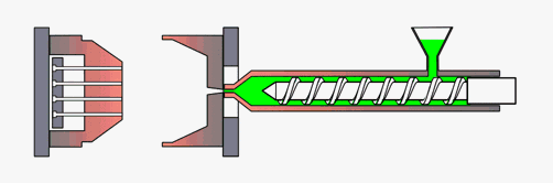
1) How does the molten resin flow during the injection and filling process?
The flow of plastic inside the cavity can be regarded as laminar flow. According to the fluid mechanics theory, the laminar fluid can be regarded as the layers of liquid next to each other slipping under the action of shearing force.
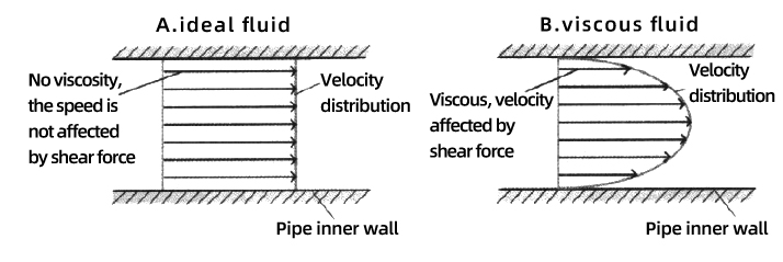
During the injection molding process, the molten resin contacts with the wall of runners (wall of mold cavity), making the stream layers adhere to the wall of runners (or wall of mold cavity) cooled firstly. The speed is zero, and there is friction resistance produced with its adjacent liquid layer. Pass on like this, the speed of the mid-stream layer is the highest. The flow form in which the laminar velocity decreases near the runner wall (or mold cavity wall) on both sides.
The middle layer is the fluid layer, and the skin layer is the solidified layer. As the cooling time goes by, the layer of curse will increase. The cross section area of fluid layer will be smaller gradually. The harder the filling, the larger the injection force. Indeed, it is more difficult to push the melt into the mold cavity to fulfill the injection.
Therefore, the size of the wall thickness has a great influence on the flow and filling of the injection molded parts during the injection molding process, and its value cannot be too small.
2) The viscosity of the plastic melt also has a great influence on the fluidity
When the melt is under the external action, and there is relative motion between the layers, there will be internal friction force generated to interfere the relative movement between the fluid layers. The inner friction force produced by the fluid is called viscosity. Evaluating the viscosity strength with the dynamic viscosity (or viscosity coefficient). Numerically the ratio of shear stress to shear rate of the melt.
The viscosity of melts reflects the characteristics of the ease with which the plastic melt flows. It is a measure of melt flow resistance. The higher the viscosity, the larger the fluid resistance, the more difficult the flow. The influential factors of melt viscosity affects not only is associated with the molecular structure, but also related to the temperature, pressure, shear rate, additives, etc. (after deciding the types of plastic materials, the temperature, pressure, shearing rate, additives and other factors during the injection molding process may be altered to change the fluidity of plastic in the injection molding process. In the future, we will write an article on the topic of liquidity depending on the situation.)
While, in the actual application, melt Index indicates to the fluidity of plastic materials in processing. The higher the value, the better the fluidity of material. On the contrary, the fluidity of material will be worse.
Therefore, plastic with good fluidity is easier to fill the mold cavity, especially for injection molding parts with complex structures.
The fluidity of commonly used plastics can be roughly divided into three categories according to the mold design requirements:
①Good fluidity: PA, PE, PS, PP, CA, poly(4) methyl pentylene;
②Medium fluidity: polystyrene series resins (such as ABS, AS), PMMA, POM, PPO;
③Poor fluidity: PC, hard PVC, PPO, PSF, PASF, fluoroplastics.
The wall thickness of material can be selected based on the difference of material and the appearance size of products, of which the range is 0.6~6.0mm normally. The commonly used wall thickness is normally between 1.5〜3.0mm. The following is the recommended value of various types of materials (wall thickness of internal bearing parts can be enlarged on the base of the Fig below).
| Plastic | Minimum wall thickness | Recommended wall thickness value — Small plastic products | Recommended wall thickness value — Medium-sized plastic products | Recommended wall thickness value — Large plastic products |
| Polyamide (PA) | 0.45 | 0.75 | 1.6 | 2.4~3.2 |
| polyethylene (PE ) | 0.5 | 1.25 | 1.6 | 2.4~3.2 |
| polystyrene (PS ) | 0.75 | 1.25 | 1.6 | 3.2~5.4 |
| Modified polystyrene (HIPS) | 0.75 | 1.25 | 1.6 | 4~6.5 |
| Plexiglass | 0.8 | 1.5 | 2.2 | 3.2~5.8 |
| Rigid (PVC) poor | 1.15 | 1.6 | 1.8 | 2.4~3.2 |
| polypropylene(PP) | 0.85 | 1.45 | 1.75 | 2.4~3.2 |
| polycarbonate(PC) poor | 0.95 | 1.8 | 2.3 | 3~4.5 |
| polyphenyl ether(PPO)Poor | 1.2 | 1.75 | 2.5 | 3~6.4 |
| Cellulose acetate (EC) | 0.7 | 1.25 | 1.9 | 3~4.8 |
| polytoluene(POM) | 0.8 | 1.40 | 1.6 | 3~5.4 |
| polysulfone(PSF) poor | 0.95 | 1.80 | 2.3 | 3~4.5 |
| ABS | 0.75 | 1.5 | 2 | 3~3.5 |
As we can see from the Fig. above, the material with the poorest fluidity, the requirements for the minimum wall thickness will be higher. This has been introduced in the laminar flow theory.
The recommended value of wall thickness above is just a conservative number. In the actual application, the sizes of the parts include small, medium and large, the above picture does not specify the reference range.
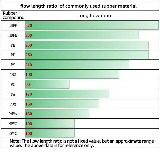
3) We can calculate by the flow length ratio
The flow length ration of plastic refers to the ratio of length (L) to wall thickness (T) of the plastic melt flow. That means for a given wall thickness, the higher the flow length ratio, the farther the plastic melt flows. Or when the length of the plastic melt flow is certain, the larger the flow length ratio, the smaller the wall thickness can be. Thus, the flow length ratio of plastic directly affects the number of feeding and distribution of plastic products. Also, it affects the wall thickness of plastic.
To be more accurate, the specific value range of the wall thickness can be obtained through the calculation of the flow length ratio. Indeed, this value is related to material temperature, mold temperature, polishing degree, etc. it is only an approximate range value, different conditions are different, it is difficult to be precise, but it can be used as a reference value.
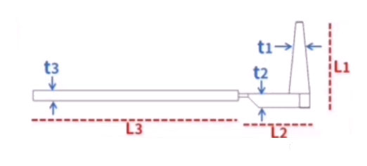
Calculation of flow length ratio:
L/T (total) = L1/T1 (main channel) + L2/T2 (split channel) + L3/T3 (product) The calculated flow length ratio should be less than the value given in the physical property table, otherwise there may be The phenomenon of poor filling.
For example
A rubber shell, PC material, wall thickness is 2, the filling distance is 200, runner is 100, diameter of runners is 5.
Calculation: L/T(total)=100/5+200/2=120
The reference value for flow length ratio of PC is 90, which is obviously higher than the referent value. The injection speed and pressure need to be increased as it is difficult to inject, or even require specific high performance injection molding machines. If adopts two feeding points or changes the feeding points position, the filling distance of products can be reduced to 100, which is L/T(total)=100/5+100/2=70. The length ratio now is less than the reference value and is easy for injection molding. L/T(total)=100/5+200/3=87 when the wall thickness is changed into 3, which allows the normal injection molding.
3. Based on the appearance principle:
The specific performance of wall thickness affecting the appearance of parts is as follows:
1) Uneven wall thickness: surface shrinkage (including appearance defects such as shrinkage, pits, thick and thin prints), warping deformation, etc.
2) Excessive wall thickness: defects such as surface shrinkage and internal shrinkage holes.
3) The wall thickness is too small: defects such as lack of glue, thimble printing, warpage and deformation.
shrinkage or porosity
shrinkage or porosity normally occurs at the thick wall thickness areas. The mechanism: according to the material solidification principle, the internal porosity and surface shrinkage during injection molding process is due to the constant contraction during the cooling process. When the shrinkage is concentrated at the frozen position behind, but cannot get be made up immediately, shrinkage and porosity are more likely to occur inside.
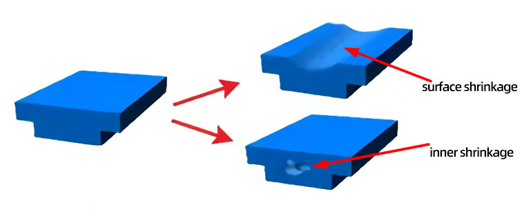
The cooling shrinkage of plastic materials include two categories: Internal concentrated shrinkage and external overall shrinkage (shrinking inward from the periphery of the injection molded part). Due to the certain shrinkage rate of plastic materials, the external overall contraction is bound to exist, which is presented as the size of parts after injection molding is smaller than the size of mold cavity. While, the internal concentrated shrinkage is the cause for the formation of surface shrinkage and internal shrinkage cavities.
Warpage
The main reason for warpage of parts is due to the uneven concentration of the formation of parts. The shrinkage difference of parts everywhere will cause the internal residual stress. During injection molding, the residual stress is higher than the strength of plastic rubber parts, the parts will be warped after de-molding. If there is an even concentration rate exit in the whole part, the warpage will not occur but only shrinkage in size. However, due to the interaction of many factors such as orientation, mold cooling, plastic part design, mold design and forming conditions, it is complex to achieve low or uniform shrinkage.
Plastic parts are warped due to uneven shrinkage, and the reasons for the change in shrinkage include:
1) uneven temperature inside the plastic parts
2) when the parts solidified, the pressure and cooling rates difference along the direction of thick wall
3) the parts are ejected when is not sufficiently cooled or the eject pin is deformed, undercut is too deep, improper ejection method, improper de-moulding slope and other factors may cause the plastic part to warp.
4) Changes in the thickness of the plastic parts lead to differences in cooling rates.
5) warpage or asymmetrical geometrical shapes in plastic parts
6) there is any difference in the materials with and without additives
7) the difference in molecular chain/fiber alignment in the flow direction and perpendicular to the flow direction results in different shrinkage rates.
8) difference in holding pressure (for example excessive packing pressure at the gate, but insufficient packing pressure away from the gate)
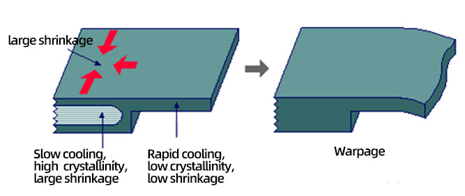
From the above reasons, the 2nd and 4th is related to the uneven wall thickness. The shrinkage difference caused by the uneven wall thickness, resulting in warping deformation of thermoplastic plastic parts without added reinforcing fillers. More specifically, the changes in section wall thickness of plastic parts normally cause the difference in the cooling rates and crystallinity, then caused the shrinkage difference and warpage. As shown in the picture below, the thin wall area is cooled first and then is thick walled area. When the difference is large, the volume shrinkage rate difference and residual stress are large. When the residual stress overcomes the strength of parts, it will cause thick and thin prints (similar to shrinkage), or seriously, warping and even cracking will occur.
Wall Thickness Design Tolerance Variation:

1) Tolerance variation = (t1-t2)/t1=25% (amorphous plastic or filled plastic)
2) Tolerance variation = (t1-t2)/t1=12.5% (pure semi-crystalline plastic)
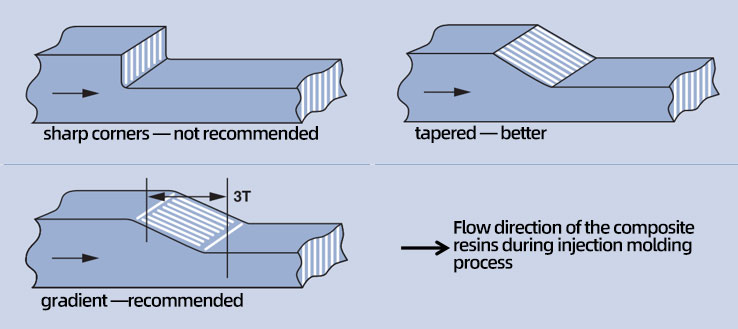
The tolerate changing amount value for the above wall thickness design is only experience value (It is generally not a problem to tolerate changes that do not exceed this value). However, according to the real situation (different materials, different structures, different injection molding coefficients). Generally speaking, if the space allowed, gradient transition is needed between the thick walls and thin walls to avoid the stress concentration. The transition length should be less than 2T (2 times of thickness). The longer the transition, the tolerance variation of wall thickness design can be larger than the above value (preferably not more than 50%).
Applications:
1) Buckle
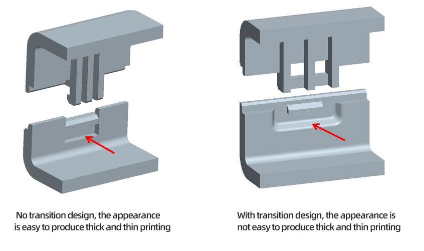
2)spigot
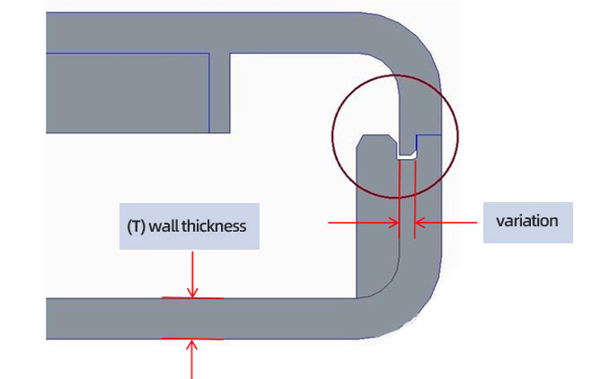
The value(variation) for female spigot is based on the original wall thickness, and it generally will not have transit design. Therefore, the value (variation) of the female stop can be selected according to the tolerance change of the above wall thickness design, no more than 50% of the wall thickness maximumly, or it is easy to produce thick and thin prints.
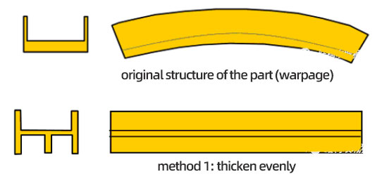
Through the even wall thickness, warpage can be effectively solved. However, not each part can achieve even wall thickness. Uneven wall thickness is unavoidable for some parts, especially for complex parts. However, structurally, it can be fixed by other methods, such as the following example.
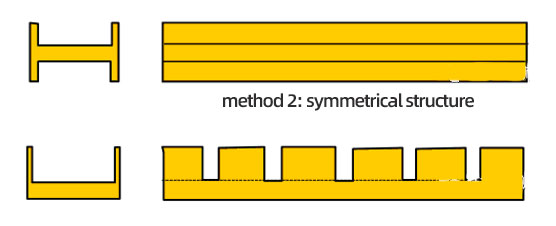
Method 3: Partial digging
Actually, the reason for most of the injection molding defects can be found from the below aspects, solving solutions can be started from the following aspects:
For example, the above-mentioned shrinkage or shrinkage cause analysis:
1) structural design: uneven wall thickness or thick wall thickness
2) mold design: thin runners, distribution of cooling pipes (localized high temperature on the mold), etc.
3) injection molding: insufficient time for pressure holding, low injection pressure, slow injection speed, etc.
4) material: the raw material is too soft.
Solution:
1) product structure: The value of wall thickness should be reasonable, and the wall thickness should be as uniform as possible. If not, it should be gradually transitioned.
2) mold design: whether the design of cooling pipes of molds are appropriate or sufficient, requiring to adjusting the mold.
3) injection molding: raise the injection molding pressure and hold the pressure for molds after the injection is finished and keep it cool sufficiently.
4) material: replacing material with low water shrinkage rate. If it cannot be replaced, it can be improved by adding additives (minerals, glass fiber, etc.)
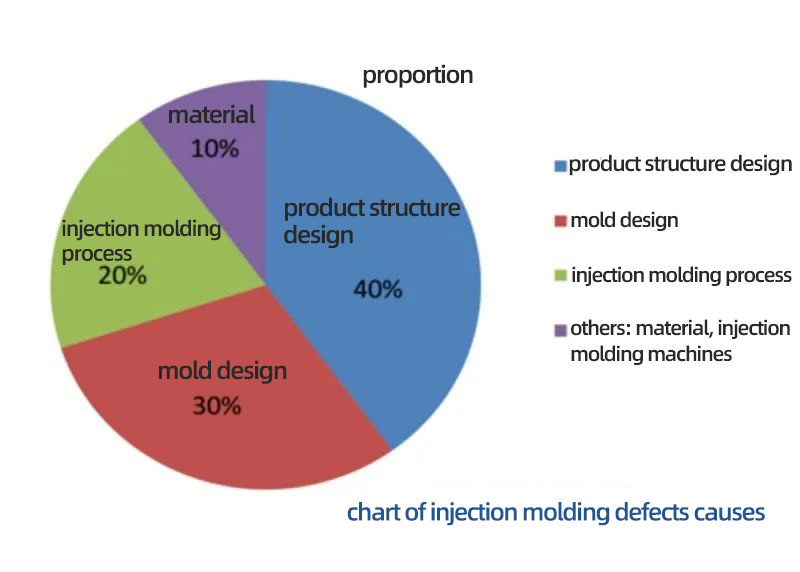
However, for most of the engineers, defects are often detected after mold testing and thus the problems are often fixed by mold manufacturers as the problems can be fixed by trying to change the injection molding coefficients, which is the most effective and cost effective. However, it is not necessary to be efficient. So, before designing, carrying out the detailed DFM is required as 70% causes of defects is in the stage of structural designing and mold designing.
4. Based on the principle of cost
Without considering the increased cost for fixing the defects due to the wall thickness, large wall thickness will only causes the waste of raw material. This is not the worst. The worse is the extension of injection molding circle caused by the increase of cooling time. The production efficiency is low and further cause the raise of cost.
For a type of injection molding product, the formation circle can be affected by different factors. For instance, filling time, time for holding pressure, time for material melting, time for molding clapping and closing. However, cooling time which is of highest importance.
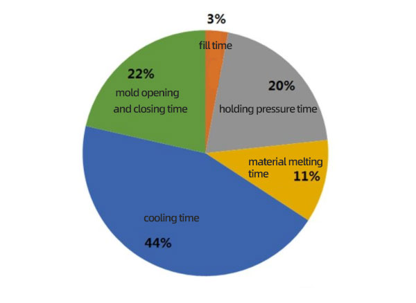
Figure: The proportion of each injection molding time
Cooling time of injection molding parts often refers to the period of time that starts from the plastic melt filling the mold cavity to the mold opening and the part is taken out. The time standards for molding opening and parts taking is often when the parts are fully cursed with a certain degrees of strength and rigidity, and the parts will not break when ejecting.
The approximate time for the injection molding cooling can be obtained through the mold flow analysis software. The following the approximate value for cooling time for commonly used plastics with different wall thickness.
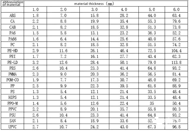
Figure: Cooling time (seconds) of different wall thicknesses of commonly used plastics
Cooling time is related to an array of factors, like raw materials, thickness of products, injection temperature, mold temperature, the number of water pipes and distribution. The calculation of cooling time does not have accurate formula. Just a rough estimate can be calculated. As the formula derivation process is complex, so we don’t talk much about it. For the same type of plastic material, it can be simplified into the following formula.
Cooling time = proportional constant * (wall thickness) squared
Thus, the relationship between cooling time and wall thickness is as a quadratic curve. Fig. 3-19 shows the relationship of the wall thickness of a type of plastic and cooling time.
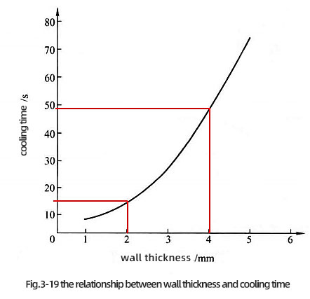
It can be seen from Fig 3-19, when the wall thickness of plastic parts is at 2mm, the cooling time is about 15s. When the wall thickness increases to 4mm, the cooling time increases to 48s, which means the formation circle increased by 33s, more than double.
If the plastic part is cavity 1*2, the cost of injection molding machine is 1yuan/min, then the cost of injection molding (estimation)= cost of an injection molding part / 60*formation circle/cavity number =1/60*33/2=0.275(yuan)
That is, the cost for each part will increase by 0.275 yuan. If the yield per year is 1 million, then the cost for each year will increase 275,000 pieces. This is the cost for only one piece. Think about it, if a complete set of products has several plastic parts with such a wall thickness, the increased cost can be imagined, the extra cost will be magnificent.
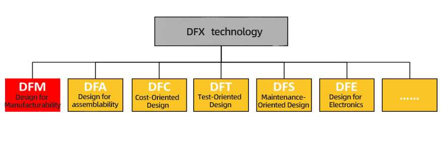
Thus, the wall thickness of plastic parts impacts greatly to the cost of plastic parts. Meanwhile, this is also the part that many engineers ignore. What important is that wall thickness must be confirmed as it is hard to change in the later stage. Thus, before mold opening, it is not just DFM (Design for Manufacturing), DFA (Design for Assembly), but also DFC (Design for Cost).
The designing principles of wall thickness above are introduce from four aspects, which are mechanical properties, formability, appearance, cost. If use one sentence to describe the design of wall thickness, that is the value of the wall thickness of the injection molded parts should be as small as possible and as uniform as possible under the condition of satisfying the mechanical properties and processing performance. If not, it should be uniformly transitioned.
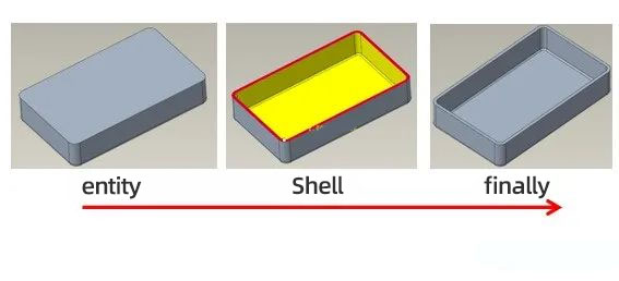
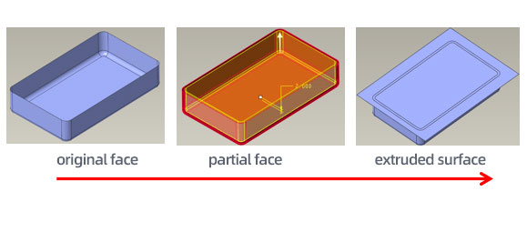
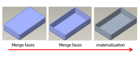
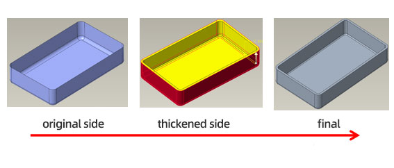
Supplement: Drawing method of wall thickness in structural design
1. Shell method: simple and practical, but whether it is successful or not depends on the quality of the surface.
2. Partial surface method: multiple steps, but it is highly changeable and can deal with more complex shapes.
3. Thickening: generally used for simple shapes.
MORE BOLG
Insert mold in injection mold service
What are advantages and disadvantages of Zinc alloy and Aluminum alloy?
Inspection standards for injection molded partappearance
How to judge the quality of your plastic products?
Inspection standards for CNC machining
To ensure that your products are 100% qualified
Categories

Try GREFEE now,for free
We keep your uploaded files confidential and secure.